background image

Installation Instructions

CPA365

5

ASSEMBLY AND INSTALLATION

WARNING:

Failure to provide adequate structural strength

for this component can result in serious personal injury or
damage to equipment!  It is the installer’s responsibility to
make sure the structure to which this component is attached
can support five times the combined weight of all equipment.
Reinforce the structure as required before installing the
component.

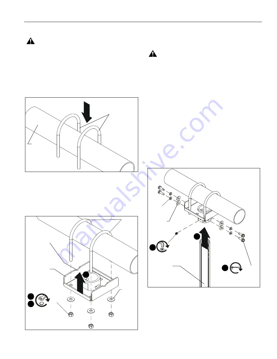
1.

Place two U-bolts (B) over 1" (minimum) steel supporting
truss or pipe. (See Figure 1)

Figure 1

2.

Raise truss plate (A) up and insert U-bolts through holes in
truss plate. (See Figure 2)

NOTE:

If installing truss plate (A) to pipe, ensure that pipe fits

into notches in plate. (See Figure 2)

Figure 2

3.

Loosely install 3/8" nuts (F) and 3/8" washers (G).

4.

Level mount and tighten nuts (E). (See Figure 2)

Installing Extension Column

WARNING:

Exceeding the weight capacity can result in

serious personal injury or damage to equipment!  It is the
installer’s responsibility to make sure the combined weight of
all components located within the mounting system of the
CPA365 does not exceed 500 lbs (226.8 kg).

1.

Route cables through extension column (not included).

2.

Install UL Listed CPA Extension Column Series (not
included) into CPA365.

NOTE:

Installation of hex head self-tapping screws will be

easier when screws are carefully aligned with holes in
extension column, and a drill and nut driver is used. If
a drill will NOT be used, a small amount of pressure will
be needed to get the self-tapping screws started.

3.

Secure extension column to CPA365 using four 5/16-18 x 1"
hex head self-tapping screws (D), four 5/16" split lock
washers (E) and four 5/16" flat washers (H) through holes in
extension column. (See Figure 3)

4.

Install one 5/16" x 1/2" set screw (C) into threaded hole,
tightening firmly against column. (See Figure 3)

Figure 3

5.

Complete installation following appropriate mount
installation instructions.

(B) x 2

Supporting
pipe

Pipe should fit
into notches

4

(F) x 4

(A)

(G) x 4

2

3

(B)

Extension
column

4

(C) x 1

(not included)

3

(D) x 4

2

(E) x 4

(H) x 4

Summary of Contents for CPA365

Page 1: ...N S T R U C T I O N S I N S T R U C T I O N S D I N S T A L L A T I O N M O N T A G E A N L E I T U N G Truss Ceiling Adapter Accessory Accessoire d adaptateur de plafond à armature Adapterzubehör für Decken mit Auslegern CPA365 ...

Page 2: ...rranty It is the installer s responsibility to make sure all components are properly assembled and installed using the instructions provided WARNING Failure to provide adequate structural strength for this component can result in serious personal injury or damage to equipment It is the installer s responsibility to make sure the structure to which this component is attached can support five times ...

Page 3: ...en Serrez les fixations Loosen Fastener Aflojar elemento de fijación Befestigungsteil lösen Desapertar fixador Allentare il fissaggio Bevestiging losdraaien Desserrez les fixations Socket Wrench Llave de cubo Steckschlüssel Chave de caixa Chiave a brugola Dopsleutel Clé à douilles Open Ended Wrench Llave de boca Gabelschlüssel Chave de bocas Chiave a punte aperte Steeksleutel Clé à fourche Hex Hea...

Page 4: ...ion Instructions 4 TOOLS REQUIRED FOR INSTALLATION PARTS 5 32 Included 1 2 1 2 1 2 nut driver 9 16 9 16 A 1 B 2 C 1 5 16 x 1 2 E 4 5 16 G 4 3 8 J 1 5 32 3 8 x 3 1 2 x 5 3 8 Truss plate D 4 5 16 18 x 1 F 4 3 8 H 4 5 16 ...

Page 5: ... damage to equipment It is the installer s responsibility to make sure the combined weight of all components located within the mounting system of the CPA365 does not exceed 500 lbs 226 8 kg 1 Route cables through extension column not included 2 Install UL Listed CPA Extension Column Series not included into CPA365 NOTE Installation of hex head self tapping screws will be easier when screws are ca...

Page 6: ... de la responsabilité de l installateur de s assurer que tous les composants sont correctement montés et installés conformément aux instructions fournies AVERTISSEMENT Une résistance structurelle non appropriée pour ce composant peut entraîner des blessures corporelles graves ou endommager l équipement Il est de la responsabilité de l installateur de s assurer que la structure à laquelle ce compos...

Page 7: ... À L INSTALLATION PIÈCES DIMENSIONS POUCES MILLIMÈTRES 4 0 mm 5 32 inclus 12 7 mm 1 2 12 7 mm 1 2 12 7 mm 1 2 tourne écrou 14 3 mm 9 16 14 3 mm 9 16 A 1 B 2 C 1 5 16 x 1 2 E 4 5 16 G 4 3 8 J 1 5 32 3 8 x 3 1 2 x 5 3 8 Plaque armature D 4 5 16 18 x 1 F 4 3 8 H 4 5 16 ...

Page 8: ...mmager le matériel Il est de la responsabilité de l installateur de s assurer que le poids combiné de tous les composants situés dans le système de montage du CPA365 ne dépasse pas 226 8 kg 500 lbs 1 Faites passer les câbles à travers la colonne d extension non incluse 2 Installez la série de colonnes d extension CPA homologuées UL non incluses dans le CPA365 REMARQUE L installation des vis autota...

Page 9: ...emente nach den beiliegenden Anweisungen montiert und installiert werden WARNUNG Wenn dieses Bauelement nicht an einer Konstruktion mit der erforderlichen Tragfähigkeit montiert wird kann dies zu schweren Verletzungen oder Geräteschäden führen Der Monteur hat dafür zu sorgen dass die Konstruktion an der das Bauelement angebracht wird über die erforderliche Tragfähigkeit verfügt Die Konstruktion mu...

Page 10: ...DERLICHES WERKZEUG TEILE ABMESSUNGEN ZOLL MILLIMETER 4 0 mm 5 32 mitgeliefert 12 7 mm 1 2 12 7 mm 1 2 12 7 mm 1 2 Mutterndreher 14 3 mm 9 16 14 3 mm 9 16 A 1 B 2 C 1 5 16 x 1 2 E 4 5 16 G 4 3 8 J 1 5 32 3 8 x 3 1 2 x 5 3 8 Auslegerplatte D 4 5 16 18 x 1 F 4 3 8 H 4 5 16 ...

Page 11: ... WARNUNG Das Überschreiten der maximalen Tragkraft kann zu schweren Verletzungen oder Geräteschäden führen Der Monteur ist dafür verantwortlich sicherzustellen dass das Gesamtgewicht aller Komponenten innerhalb des Halterungssystems des CPA365 226 8 kg 500 lbs nicht überschreitet 1 Führen Sie die Kabel durch die Ausziehsäule nicht mitgeliefert 2 Montieren Sie eine Ausziehsäule der UL konformen CPA...

Page 12: ...instraat 14 6003 DK Weert Netherlands P 31 0 495 580 852 F 31 0 495 580 845 Asia Pacific A Office No 1 on 12 F Shatin Galleria 18 24 Shan Mei Street Fotan Shatin Hong Kong P 852 2145 4099 F 852 2145 4477 Chief Manufacturing a products division of Milestone AV Technologies 8800 002412 Rev00 2013 Milestone AV Technologies a Duchossois Group Company www chiefmfg com 05 13 ...

Reviews: