Installation Instructions
K4G220-320
9
Figure 10
5.
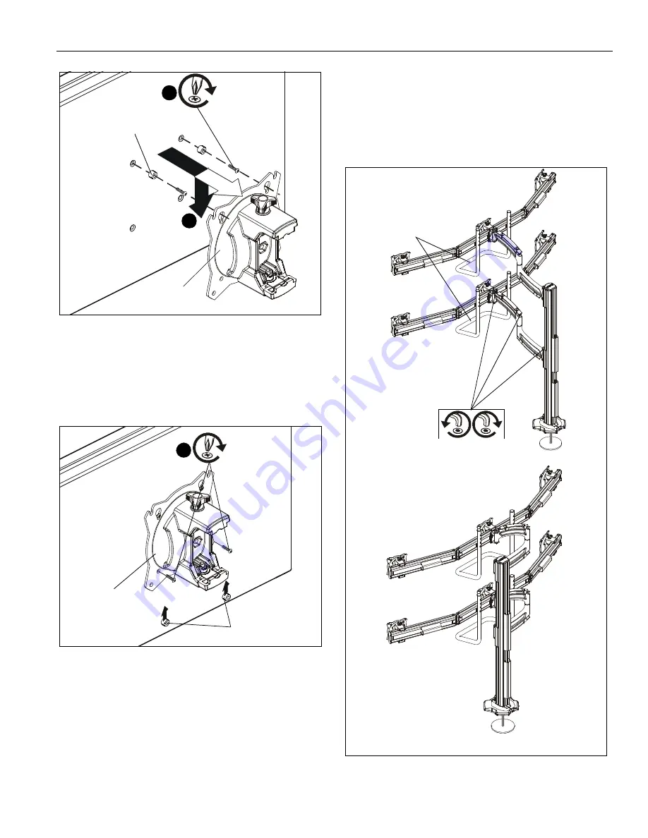
Slide two remaining selected spacers (F4 or F5) in between
faceplate and display, positioning them over the
lower
two
mounting holes. (See Figure 11)
6.
Install two remaining selected screws (F1 or F2) through
lower
two mounting holes on faceplate, selected spacers
(F4 or F5) into the
lower
mounting holes on the display. (See
Figure 11)
Figure 11
7.
Tighten all four screws. Do not over-tighten!
Adjustments
Pivot Adjustment (Column Arm)
1.
Use handles (G) to extend or collapse column arms as
desired. (See Figure 12)
2.
(Optional) Loosen or tighten column arm pivot tension
screws as desired to increase or decrease pivot tension.
(See Figure 12)
Figure 12
(F4 or F5) x 2
(F1 or F2) x 2
3
faceplate
(array arm not shown for clarity)
4
(F4 or F5) x 2
(F1 or F2) x 2
6
faceplate
(array arm not
shown for clarity)
arms extended
arms collapsed
pivot tension
screws
(K4G320 shown)
(G) x 2


