Installation Instructions
MSP-BBSP
3
INSPECT THE UNIT BEFORE INSTALLING
WARNING: Watch for pinch points. Do not put your fingers
between movable parts.
1.
Carefully inspect the mount for shipping damage. If any dam-
age is apparent, call your carrier claims agent and do not con-
tinue with the installation until the carrier has reviewed the
damage.
NOTE:
Read all instructions before starting installation.
2.
Lay out components to ensure you have all the required parts
before proceeding (see drawing on page 2).
INSTALLATION
WARNING: It is the responsibility of the installer to verify that
the structure to which the mount is anchored will
safety support five times the combined load of all
attached components and equipment.
1.
Determine the exact mounting location prior to installation,
considering the unit’s swing radius.
2.
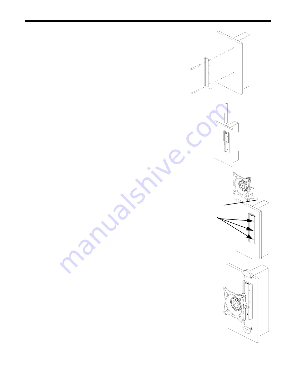
Using the wall plate as a template, drill two 3/32” pilot holes to
a minimum depth of 1 1/2” into wall stud.
3.
Using two Phillips head #10 wood screws (supplied), secure
the wall plate (see Figure 1).
4.
Install screw cover (see Figure 2).
5.
Check mount to insure it is level and adjust to level if neces-
sary.
6.
Determine if you are installing a VESA compliant flush mount
display, VESA compliant recessed mount display or a non-
VESA compliant display and follow the appropriate instruc-
tions.
VESA Compliant Flush Mounting
A.
Install the mount on the wall plate, set to desired height at
one of the fixed height settings and secure by tightening
the set screw (see Figure 3).
B.
Install the end caps on the wall plate (see Figure 4).
CAUTION:
If monitor uses a screw size other than M4, DO NOT
use the M4 screws provided. Using the wrong screws
could result in damage to your display.
C.
Start two M4 X 12mm Phillips pan head screws in the top
mounting holes of your display.
D. Matching the hole pattern on your display with the hole
pattern on the mount (see Figure 5), hang the mount from
the two screws started in Step A.
Figure 1. Secure Wall Plate
Figure 2. Install Screw Cover
Figure 3. Install iC-SP-TP1
and Tighten Set Screw
Fixed Height Settings
Set Screw
Figure 4. Install End Caps
Summary of Contents for MSP-BBSP
Page 1: ......


