MSP-CSC11
Installation Instructions
6
Assembly And Installation
Cart Assembly
CAUTION:
Attachment holes may be damaged if a power
drill is used to insert button head cap screws. Screws should
first be inserted and turned BY HAND with the hex key or with
a handheld screwdriver BEFORE using a hex head drill bit
and power drill (optional) to complete the attachment.
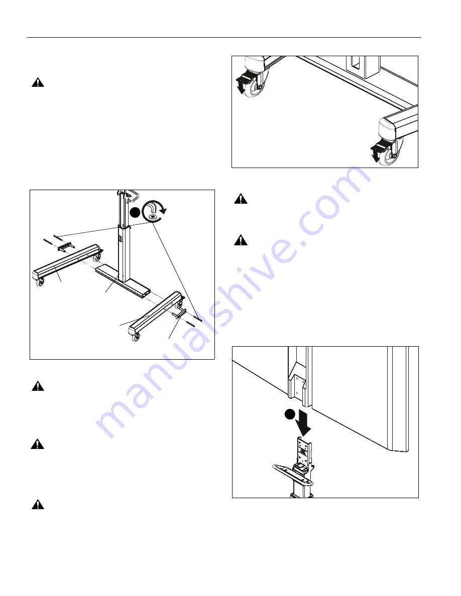
1.
Assemble two legs (A and B) to the column assembly (D)
using two 5/16-18 x 4-1/4" button head cap screws (E) and
one end cap (C) per leg. (See Figure 1)
NOTE:
When attaching the legs, make sure the larger holes
are on the outside and the smaller holes on the inside.
Figure 1
CAUTION:
INNER COLUMN IS SHIPPED DISENGAGED
and may pinch hands! Hold both inner and outer posts
(columns) while removing from box.
Display Installation
WARNING:
Exceeding the weight capacity can result in
serious personal injury or damage to equipment! It is the
installer’s responsibility to make sure the combined weight of
all components located between the MSP-CSC11 up to (and
including) the display does not exceed 75 lbs (34 kg).
CAUTION:
Before attaching display to cart set the brakes
on the back wheels by pressing down on the tab. (See
Figure 2)
Figure 2
WARNING:
DISPLAY WEIGHS UP TO 75 LBS! Always
use two people and proper lifting techniques when installing
or positioning display on cart.
WARNING:
The MSP-CSC11 mounting cart has been
designed specifically for Cisco’s MX200 and MX300 flat
panel display. DO NOT attempt to mount any other display to
this mounting cart!
For MX200 Installation
NOTE:
For MX300 Installation, proceed to MX300 Installation
Section.
1.
Carefully slide display onto column assembly (D). (See
Figure 3)
Figure 3
(Front view of cart)
(E) x 4
(C) x 2
(D)
(A) x 1
(B) x 1
1
(rear view of cart)
1
(MX200 install)


