background image

Installation Instructions

MSPFB3

5

Mount Installation

WARNING:

IMPROPER INSTALLATION CAN LEAD TO

MOUNT FALLING CAUSING SERIOUS PERSONAL
INJURY OR DAMAGE TO EQUIPMENT! It is the installer’s
responsibility to make sure the structure to which the mount
is being installed is capable of supporting five times the
combined weight of the mount and all attachments.

MOUNT ASSEMBLY

The only assembly required on the MPWU is attaching a cable
management clip to each side of the mount face plate and four
end caps the the mount wall plates.

To attach the wall plate end caps:

1.

Slide one end cap (F) into each end of upper and lower wall
plates ON MOUNT (A). (See Figure 2)

Figure 2

To attach the cable management clips:

1.

Pull mount face plate outward until access to rear of face
plate can be achieved.

2.

Install two cable management clips (B) into each side of
mount faceplate. (See Figure 3)

Figure 3

MOUNT INSTALLATION

WARNING:

The installer is responsible for verifying that

the structure to which the mount is anchored will safely
support five times the combined load of the mount and all
attached components.

To install mount:

1.

Identify appropriate mounting location.

2.

Locate studs.

NOTE:

The MPWU is designed to be mounted on 16" on

center wood studs.

3.

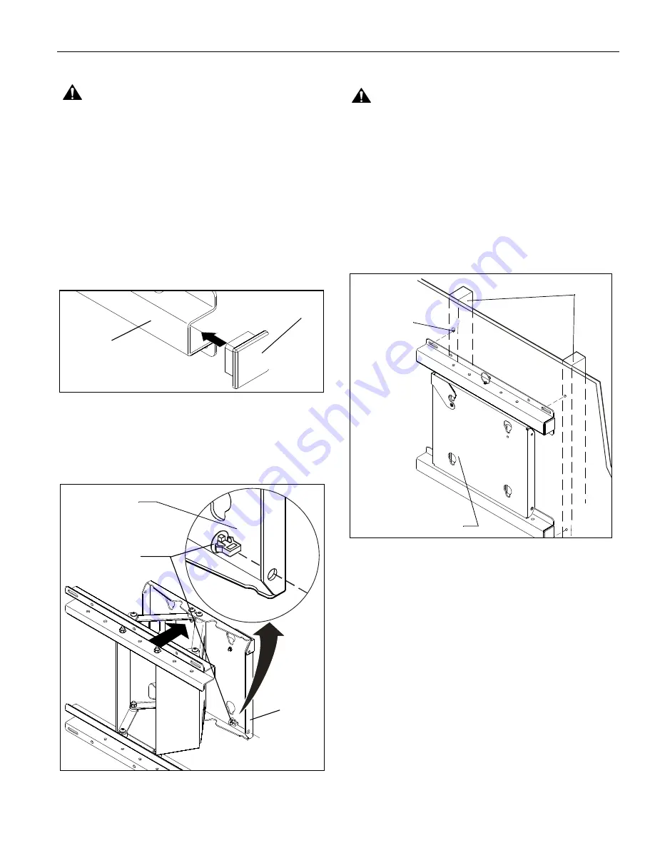
Place mount assembly (A) against wall, level mount, and
mark four pilot hole locations (See Figure 4).

4.

Drill four pilot holes, at marked locations. (See Figure 4).

Figure 4

5.

Place mount assembly (A) against wall and align mounting
holes in mount assembly with pilot holes (See Figure 5).

6.

Secure mount (A) to wall studs using four wood screws, and
four flat washers.

(A) x 1

(F) x 4

Face Plate

Face Plate

(B) x 2

.200" Pilot Hole
(Mark and Drill)

Wall Studs

(A) x 1

Summary of Contents for MSPFB3

Page 1: ...truções de Instalação Istruzioni di installazione Installatie instructies Instructions d installation Medium Flat Panel Wall Mount Spanish Product Description German Product Description Portuguese Product Description Italian Product Description Dutch Product Description French Product Description MSPFB3 ...

Page 2: ...ult in serious personal injury damage to equipment or voiding of factory warranty It is the installer s responsibility to make sure all components are properly assembled and installed using the instructions provided WARNING Failure to provide adequate structural strength for the installation of this kit can result in serious personal injury or damage to equipment It is the installer s responsibili...

Page 3: ...Installation Instructions MSPFB3 3 TOOLS REQUIRED FOR INSTALLATION AND PARTS x1 I M 200 Ø 5mm E 1 10 24 B 2 A 1 F 4 K 1 C 2 G 1 D 1 10 24 x 1 2 J 1 H 1 ...

Page 4: ...MSPFB3 Installation Instructions 4 DIMENSIONS Figure 1 ...

Page 5: ...ntil access to rear of face plate can be achieved 2 Install two cable management clips B into each side of mount faceplate See Figure 3 Figure 3 MOUNT INSTALLATION WARNING The installer is responsible for verifying that the structure to which the mount is anchored will safely support five times the combined load of the mount and all attached components To install mount 1 Identify appropriate mount...

Page 6: ...igure 7 5 Move display forward until all four mounting buttons are through teardrop mounting holes in faceplate and recessed area of mounting buttons is aligned with the lower area of teardrop mounting holes in faceplate 6 Lower display until the recessed area of all four mounting buttons is seated in the lower area of teardrop mounting holes in faceplate See Figure 7 7 Move latching flag to the U...

Page 7: ...e mount See Figure 9 Six on mount top and six on mount bottom Points 1 through 6 control mount extension and retraction tension Points 1 and 6 control mount right left swing tension and points 3 and 4 control display left right rotation tension NOTE It is important that correspnding points are adjusted equally Example 1 and 6 2 and 5 3 and 4 and their corresponding adjustment points on mount botto...

Page 8: ...952 894 6918 Europe A Fellenoord 130 5611 ZB EINDHOVEN The Netherlands P 31 40 2668620 F 31 0 40 2668615 Asia Pacific A Room 30I Block D Lily YinDu International Building LuoGang BuJi Town Shenzhen CHINA Post Code 518112 P 86 755 8996 9226 8996 9236 8996 9220 F 86 755 8996 9217 8832 000227 2007 Chief Manufacturing www chiefmfg com 05 07 ...

Reviews: