MSPFB3
Installation Instructions
6
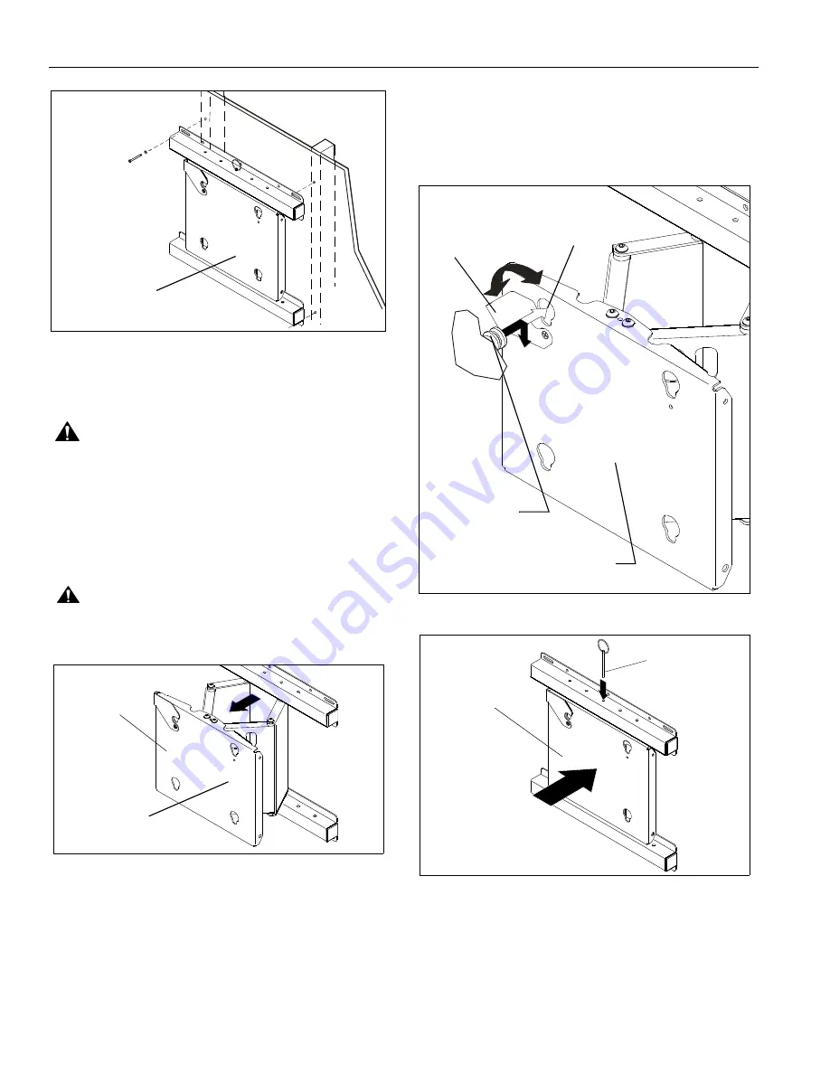
Figure 5
INSTALL DISPLAY
1.
Install interface bracket (F) follow the installation
instructions included with the bracket.
WARNING:
IMPROPER INSTALLATION CAN LEAD TO
MOUNT FALLING CAUSING SEVERE PERSONAL INJURY
OR DAMAGE TO EQUIPMENT. Displays can weigh in
excess of 40 lbs (18.1kg). ALWAYS use two people and
proper lifting techniques when installing display.
2.
Lower latching flag. (See Figure 7)
3.
Move mount faceplate to extended position by grasping
faceplate and pulling outward away from wall.
(See Figure 6)
CAUTION:
Keep hands and fingers away from all pinch
points when moving the mount from retracted to extended
position.
Figure 6
4.
Align mounting buttons on display with teardrop mounting
holes in mount faceplate (See Figure 7).
5.
Move display forward until all four mounting buttons are
through teardrop mounting holes in faceplate, and recessed
area of mounting buttons is aligned with the lower area of
teardrop mounting holes in faceplate.
6.
Lower display until the recessed area of all four mounting
buttons is seated in the lower area of teardrop mounting
holes in faceplate. (See Figure 7)
7.
Move latching flag to the UP position to secure display to
mount assembly.
NOTE:
If desired, install optional security screw and locknut
provided. The display can also be locked in the
retracted position by installing the optional locking pin
provided. (See Figure 8)
Figure 7
Figure 8
FELT PAD INSTALLATION
Felt pads (C) are provided to protect the display from
contact with the mount.
To install protective felt pads:
1.
Move display to fully extended position.
(A) x 1
Faceplate
(A) x 1
Faceplate
Mounting Button
Latching Flag
Teardrop
Mounting Hole
(4 places)
(On Display)
Locking Pin
Faceplate


