PAC-Y3
Installation Instructions
6
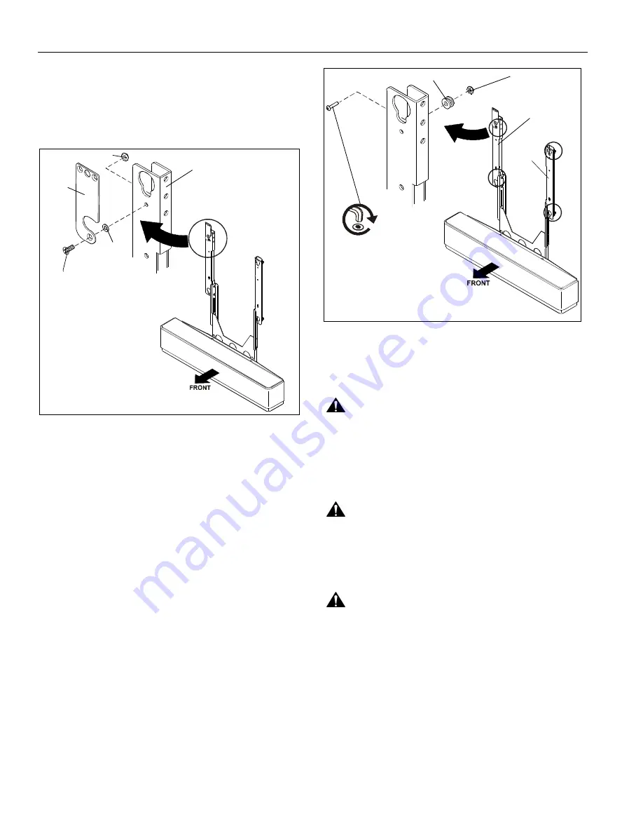
Latching Flag Assembly to Speaker Adapter
1.
Assemble one Phillips machine screw (RB) through latching
flag (RA) and spacer (RC). (See Figure 8)
2.
Secure latching flag to left speaker mounting support (B)
using one Nylock nut (RD). (See Figure 8)
Figure 8
Assemble Mounting Buttons to Speaker
Brackets
1.
Attach two mounting buttons (H) through the upper and
lower holes in right speaker mounting support (C) using two
10-24 x 7/8" button head cap screws (M) and two Nylock
nuts (Q). (See Figure 9)
2.
Attach two mounting buttons (H) through the upper and
lower holes in left speaker mounting support (B) using two
10-24 x 7/8" button head cap screws (M) and two Nylock
nuts (Q). (See Figure 9)
Figure 9
MOUNT INSTALLATION
WARNING:
IMPROPER INSTALLATION CAN LEAD TO
MOUNT FALLING CAUSING SEVERE PERSONAL INJURY
OR DAMAGE TO EQUIPMENT! It is the installers
responsibility to make certain the structure to which the
mount is being attached is capable of supporting five times
the weight of the PACY3 and all attached equipment not to
exceed 30 lbs (13.61 kg).
WARNING:
ELECTRICAL SHOCK HAZARD! CUTTING
OR DRILLING INTO ELECTRICAL CORDS OR CABLES
CAN CAUSE DEATH OR SERIOUS PERSONAL INJURY!
ALWAYS make certain area behind mounting surface is free
of electrical wires and cables before drilling or installing
fasteners.
WARNING:
EXPLOSION AND FIRE HAZARD! CUTTING
OR DRILLING INTO GAS PLUMBING CAN CAUSE DEATH
OR SERIOUS PERSONAL INJURY! ALWAYS make certain
area behind mounting surface is free of gas, water, waste, or
any other plumbing before cutting, drilling, or installing
fasteners.
(RB)
(RA)
(RC)
(RD)
(B)
(B)
(C)
(M) x 4
(H) x 4
(Q) x 4


