background image

Installation Instructions

PACHFK2

5

INSTALLATION

WARNING:

IMPROPER INSTALLATION CAN RESULT IN

DEATH OR SERIOUS PERSONAL INJURY! This accessory
should be installed by qualified personnel.

IMPORTANT ! :

The following installation procedure

assumes that a Chief PAC502 In-Wall Enclosure has
been purchased and is available for use during this
procedure. Dimensions for creating an opening in the
wall without having the PAC-502 as a template can be
found below.

Site Preparation

Locate and Prepare Mounting Site

IMPORTANT ! :

This accessory is designed for in-wall

installation spanning a minimum of three wood studs, 16"
on center. Installation of this accesory and the PAC-502
in 2" x 4" wood stud wall results in nearly direct contact
with vertical studs and back wall. Inadequate space will
remain for electrical wires/cables, plumbing, ductwork, or
insulation. Locate installation accordingly.

1.

Identify a suitable wall location for the in-wall enclosure.

WARNING:

ELECTRICAL SHOCK HAZARD!  CUTTING

OR DRILLING INTO ELECTRICAL WIRES OR CABLES
CAN CAUSE DEATH OR SERIOUS PERSONAL INJURY!
ALWAYS make certain area behind mounting surfaces is free
of electrical wires and cables before cutting, drilling, or
installing fasteners.

WARNING:

EXPLOSION AND FIRE HAZARD!  CUTTING

OR DRILLING INTO GAS PLUMBING CAN CAUSE DEATH
OR SERIOUS PERSONAL INJURY!  ALWAYS make certain
area behind mounting surfaces is free of gas, water, waste, or
any other plumbing before cutting, drilling, or installing
fasteners.

2.

Using a stud sensor, locate and mark studs.

3.

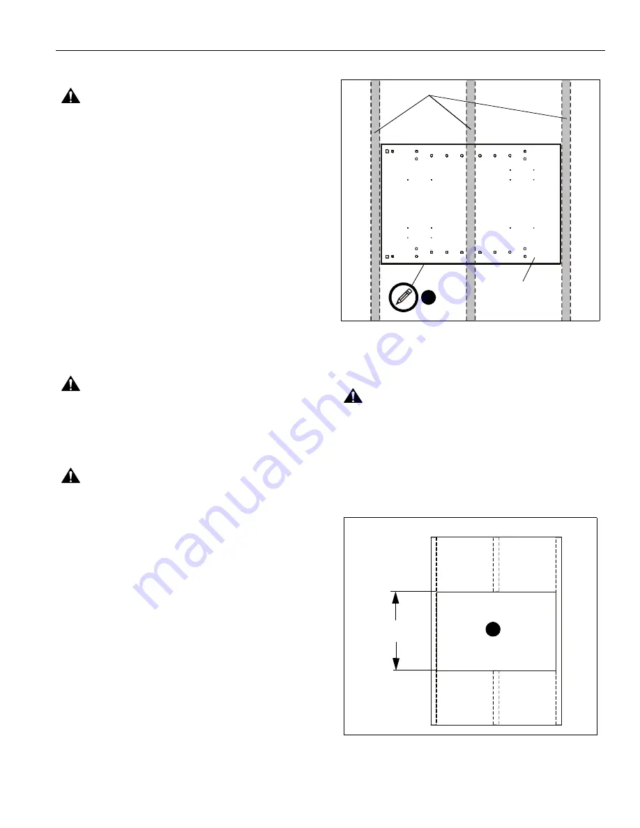
Center and level PAC502 housing between marked studs.
(See Figure 1)

4.

Using PAC502 housing as a template, draw pencil line
around housing. (See Figure 1)

NOTE:

If the PAC502 is not available mark opening to height

dimension (See Figure 2) and to inside stud edge on
either side.

5.

Cut drywall on

outside

 edge of line and remove drywall.

(See Figure 1) and (See Figure 2)

Figure 1

Install PACHFK2 Frame Support Brackets

The exposed portion of the center wood stud must be removed.

WARNING:

STRUCTURAL FAILURE HAZARD! FAILURE

TO TAKE ADEQUATE PRECAUTIONS CAN LEAD TO
DEATH OR SERIOUS INJURY! Ensure removal of center
stud will not cause unacceptable loss of structural strength.
Consult a qualified building contractor and applicable building
codes. (See Figure 2)

1.

Remove exposed portion of center stud flush with upper
and lower drywall edges. (See Figure 2)

Figure 2

Wood Studs

PAC-502

4

20.375"

5

Summary of Contents for PACHFK2

Page 1: ...O N I N S T R U C T I O N S Instrucciones de instalación Installationsanleitung Instruções de Instalação Istruzioni di installazione Installatie instructies Instructions d installation IN WALL ENCLOSURE FRAMING KIT PACHFK2 ...

Page 2: ...lerts you to the possibility of damage or destruction of equipment if you do not follow the corresponding instructions WARNING Failure to read thoroughly understand and follow all instructions can result in serious personal injury damage to equipment or voiding of factory warranty It is the installer s responsibility to make sure all components are properly assembled and installed using the instru...

Page 3: ...Chave de bocas Chiave a punte aperte Steeksleutel Clé à fourche By Hand A mano Von Hand Com a mão A mano Met de hand À la main Hex Head Wrench Llave de cabeza hexagonal Sechskantschlüssel Chave de cabeça sextavada Chiave esagonale Zeskantsleutel Clé à tête hexagonale Pencil Mark Marcar con lápiz Stiftmarkierung Marcar com lápis Segno a matita Potloodmerkteken Marquage au crayon Drill Hole Perforar...

Page 4: ...llation Instructions 4 TOOLS REQUIRED FOR INSTALLATION PARTS 3 16 Included M4 Allen Head Bit Included A 2 B 4 08 x 1 1 2 C 16 M7 x 40mm F 8 5 16 18 x 5 8 E 8 1 4 G 1 3 16 D 1 M4 Allen Head Bit Header footer brackets ...

Page 5: ... behind mounting surfaces is free of electrical wires and cables before cutting drilling or installing fasteners WARNING EXPLOSION AND FIRE HAZARD CUTTING OR DRILLING INTO GAS PLUMBING CAN CAUSE DEATH OR SERIOUS PERSONAL INJURY ALWAYS make certain area behind mounting surfaces is free of gas water waste or any other plumbing before cutting drilling or installing fasteners 2 Using a stud sensor loc...

Page 6: ...4 Figure 5 4 Make sure upper and lower brackets are level and there is a minimum of 20 375 between them at bracket centers and at both ends of brackets 5 Secure upper and lower brackets to center studs using four 08 x 1 1 2 Phillips flat head wood screws B at center studs See Figure 6 6 Secure upper and lower brackets to side studs using sixteen M7 x 40mm connector screws C and M4 Allen head bit D...

Page 7: ...ackets A See Figure 7 Figure 7 8 Secure PAC 502 enclosure to brackets using eight 1 4 flat washers E and eight 5 16 18 x 5 8 button head cap screws F using the 3 16 hex wrench G See Figure 8 CAUTION PAC 502 enclosure must be secured on both sides to side studs using lag screws and bushings following the installation instructions provided with the PAC502 accessory Figure 8 7 F x 8 E x 8 8 ...

Page 8: ...p Company www chiefmfg com 09 10 USA International A 8401 Eagle Creek Parkway Savage MN 55378 P 800 582 6480 952 894 6280 F 877 894 6918 952 894 6918 Europe A Fellenoord 130 5611 ZB EINDHOVEN The Netherlands P 31 0 40 2668620 F 31 0 40 2668615 Asia Pacific A Office No 1 on 12 F Shatin Galleria 18 24 Shan Mei Street Fotan Shatin Hong Kong P 852 2145 4099 F 852 2145 4477 ...

Reviews: