background image

Installation Instructions

PTS SERIES

5

ASSEMBLY AND INSTALLATION

WARNING:

FAILURE TO PROVIDE ADEQUATE

STRUCTURAL STRENGTH FOR THIS COMPONENT CAN
RESULT IN SERIOUS PERSONAL INJURY OR DAMAGE
TO EQUIPMENT!  It is the installer’s responsibility to make
sure the structure to which this component is attached can
support five times the combined weight of all equipment.
Reinforce the structure as required before installing the
component.

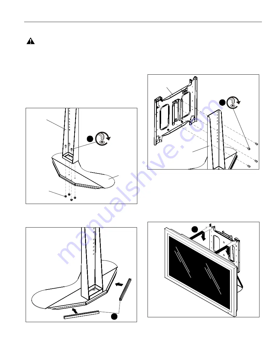
Attaching Post Assembly to Base Assembly

1.

Using four 5/16-18 x 5/8" button head cap screws (F) and
four 5/16-18 Nylock nuts (G), secure post assembly (B) to
base assembly (D). (See Figure 1)

Figure 1

2.

Attach edge trim pieces (C) to the base assembly (D). See
Figure 2.

Figure 2

Attaching Faceplate Assembly

1.

Align mounting holes in faceplate assembly (A) with holes
in post assembly (B). (See Figure 3)

NOTE:

The faceplate assembly can be placed within a four

inch range on the post assembly, dependent on size of
display.

2.

Attach faceplate assembly to post assembly using four
5/16-18 x 5/8" button head cap screws (F). (See Figure 3)

Figure 3

Attaching Interface Bracket to Display

1.

Attach interface bracket to display following instructions
included with interface bracket kit.

Attaching Display to Mount

1.

While supporting both sides of display, align four mounting
buttons on display or interface bracket with four mounting
holes in mount. (See Figures 4 and 5)

Figure 4

1

(F) x 4

(G) x 4

(D)

(B)

(C) x 2

2

2

(F) x 4

(A)

(B)

1

Summary of Contents for PTS Series

Page 1: ...I N S T A L L A T I O N I N S T R U C T I O N S Large Flat Panel Display Table Stand PTS SERIES ...

Page 2: ...sult in serious personal injury damage to equipment or voiding of factory warranty It is the installer s responsibility to make sure all components are properly assembled and installed using the instructions provided WARNING Failure to provide adequate structural strength for this component can result in serious personal injury or damage to equipment It is the installer s responsibility to make su...

Page 3: ... Chave de bocas Chiave a punte aperte Steeksleutel Clé à fourche By Hand A mano Von Hand Com a mão A mano Met de hand À la main Hex Head Wrench Llave de cabeza hexagonal Sechskantschlüssel Chave de cabeça sextavada Chiave esagonale Zeskantsleutel Clé à tête hexagonale Pencil Mark Marcar con lápiz Stiftmarkierung Marcar com lápis Segno a matita Potloodmerkteken Marquage au crayon Drill Hole Perfora...

Page 4: ...PTS SERIES Installation Instructions 4 PARTS TOOLS REQUIRED FOR INSTALLATION A 1 B 1 C 2 D 1 E 1 3 16 F 8 5 16 18 x 5 8 G 4 5 16 18 3 16 Provided 1 2 ...

Page 5: ...e 1 Figure 1 2 Attach edge trim pieces C to the base assembly D See Figure 2 Figure 2 Attaching Faceplate Assembly 1 Align mounting holes in faceplate assembly A with holes in post assembly B See Figure 3 NOTE The faceplate assembly can be placed within a four inch range on the post assembly dependent on size of display 2 Attach faceplate assembly to post assembly using four 5 16 18 x 5 8 button h...

Page 6: ...move bolt or padlock from faceplate if used See Figure 6 NOTE The pin may have been used as a more permanent locking device If so remove nut and pin and move from the lower holes to the upper holes 3 Pull back on flag on upper mounting hole and press pin down into Open position See Figure 6 WARNING THE DISPLAY MAY WEIGH IN EXCESS OF 40 LBS EACH Always use two people and proper lifting techniques w...

Page 7: ... screws from back of post assembly inserted in Step 2 of Attaching Faceplate Assembly section 3 Locate rolltension adjustment nut on back of faceplate See Figure 8 Figure 8 4 Partially loosen or tighten the roll tension adjustment nut as needed 5 Re install the faceplate assembly onto the post assembly following instructions in Attaching Faceplate Assembly section 6 Re mount the display following ...

Page 8: ...2 894 6918 Europe A Fellenoord 130 5611 ZB EINDHOVEN The Netherlands P 31 0 40 2668620 F 31 0 40 2668615 Asia Pacific A Room 30I Block D Lily YinDu International Building LuoGang BuJi Town Shenzhen CHINA Post Code 518112 P 86 755 8996 9226 8996 9236 8996 9220 F 86 755 8996 9217 8800 000016 Rev F 2007 Chief Manufacturing www chiefmfg com 07 07 ...

Reviews: