


Installation Instructions
PWC-2000
9
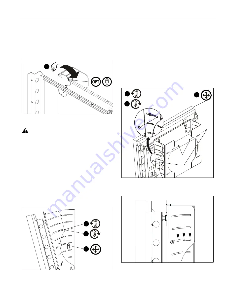
4.
Rotate Q-Latch to the CLOSED position (See Figure 9).
NOTE:
If Q-Latch does not fully close, ensure mounting
buttons are fully seated in the button openings.
NOTE:
OPTIONAL: A hole is provided in both the Q-Latch and
the front plate to accommodate the insertion of a
padlock or similar locking device.
Figure 9
WARNING:
Make sure the latch securing the display is fully
closed at all times except when removing or installing the
display. The latch must be fully closed when installing or
removing cables from the display.
5.
Attach all cables to display and CPU.
TILT ADJUSTMENT
If desired, the display may be tilted to any position between 0°
and 15°.
1.
Using key (F),
slightly
loosen upper front plate attach
screws (See Figure 10). Do NOT remove screws!
2.
Tilt display to desired angle.
3.
Tighten upper attach screws.
Figure 10
TILT LOCK
If desired, the display may be locked at 0°, 5°, or 10°.
NOTE:
A positive stop exists at 15° without the use of tilt lock
screws.
1.
Using key (F),
slightly
loosen the upper front plate attach
screws (See Figure 10). Do NOT remove screws.
2.
Using key (F), loosely install screw (B) through slot in front
plate and applicable open tilt lock hole in side plate, into nut
(D) (See Figure 11)(See Figure 12). Repeat for opposite
side.
3.
Tilt display until lock is reached.
4.
Tighten all four screws: upper front plate attach, and (B).
Figure 11
Figure 12
4
1
2
3
x2
x2
2
3
4
(B, D) x2
(B, D) x2
D
B
0°
5°
10°


