background image

Installation Instructions

 Model MSP-SPWH (PWH™)

11

Swing Arm Tension Adjustment

Swing arm tension is pre-set at the factory and is 
adjusted to accommodate displays with weights near the 
top of the mounts capacity.

If smaller displays are used it may be difficult to 
reposition the display after mounting. Swing arm tension 
can be adjusted to compensate for smaller display by:

NOTE:   

The display must be mounted prior to adjusting 

swing arm tension.

1.

Locate the ajustment bar and wrench provided with 
the mount. 

2.

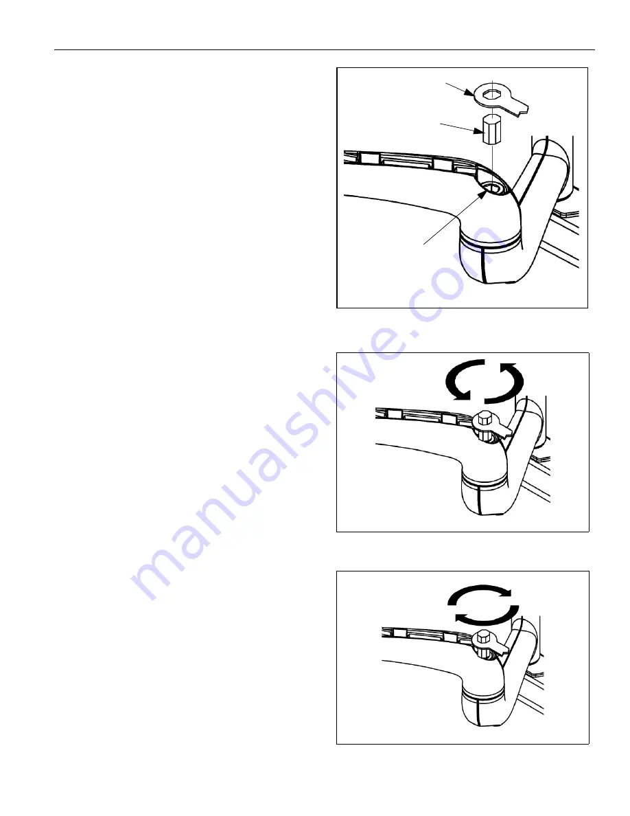
Place adjustment bar into socket head cap screw 
located at swing arm pivot point. (See figure 15)

NOTE:   

The display may need to be repositioned in order 

to gain access to the tension adjustment 
screw(s).

3.

Using the wrench provided with the mount, turn 
adjustment bar clockwise to increase swing arm 
tension or counterclockwise to reduce swing arm 
tension. (See figure 16)  and  (See figure 17)

NOTE:   

Small adjustments of 1/8 turn or less are typically 

all that is required to achieve desired tension.

4.

Check swing arm tension. If desired tension is 
present, tension adjustment is complete. If additional 
tension adjustment is required, repeat steps 2 and 3 
until desired tension is achieved.

NOTE:   

If changing from a smaller display to a larger 

displait may be necessary to increase swing Arm 
tension.

Figure 15:  Pivot Arm Tension Adjustment Location

Figure 16:  Reduce Swing Arm Tension

Figure 17:  Increase Swing Arm Tension

Adjustment
Bar

Wrench

Socket Head
Capscrew

Reduce

Increase

Summary of Contents for PWH MSP-SPWH

Page 1: ...mb line and drilling pilot holes into a single wall stud the installer installs the mount on the wall using lag bolts and washers Next the installer mounts the display and connects the power audio video cables which are diverted into the built in path in the flexible swing arm After making the lateral rotational and tilt adjustments the installation process is complete CAUTION To prevent damage to...

Page 2: ...ad of all attached components or other equipment WARNING The weight of the display placed on the mount must not exceed 100 lbs 45 36kg the maximum load capacity of the mount WARNING Watch for pinch points Do not put your fingers between movable parts WARNING Make sure the mount and brackets are correctly oriented WARNING Make sure the flag securing the display is completely lowered at all times ex...

Page 3: ...Installation Instructions Model MSP SPWH PWH 3 DIMENSIONAL DRAWING ...

Page 4: ...oes not include the PSB interface bracket INTERFACES Table 2 lists the interface for the MSP SPWH TOOLS REQUIRED FOR INSTALLATION Allen wrench set Drill and bit set Wrench set NOTE Other tools may be required depending on the method of installation PARTS LIST Unpack the carton and verify the contents listed in Table 3 on page 4 If you are missing any of the listed parts contact ustomer Service at ...

Page 5: ...unt the mount see figure 1 3 Draw a level line to indicate the desired height of the top mounting bracket 4 With an assistant lift and hold the mount against wall NOTE The mount can be fastened to the wall stud using any parallel set of mounting holes on the top and bottom brackets 5 Select the mounting holes on the top bracket and bottom where the lag bolt will be installed see figure 2 Use a pen...

Page 6: ...ole previously drilled See Figure 3 for an example a If you used a 7 32 drill bit use 5 16 lag bolts and 5 16 flat washers minimum b If you used a 9 32 drill bit use 3 8 lag bolts and 3 8 flat washers minimum 3 Repeat Step 2 to install a lag bolt using the same mounting hole in the bottom bracket 4 Tighten the lag bolts Install Cover Plates and End Caps 1 Install cover plates 20 over the top and b...

Page 7: ...e 7 4 Attach mounting bracket to the display see figure 8 as follows a For 32 screens use the M5 screws b For 42 screens use the M6 screws Figure 5 Mounting Button Attachment Figure 6 Mounting Button Location Figure 7 Bracket Hole Location Figure 8 Bracket Attachment Location REF DESCRIPTION QTY 10 Plasma Bracket 1 20 10 24 x 1 2 Button Head Cap Screw 4 30 M5 x 20mm Button Head Cap Screw 4 40 M6 x...

Page 8: ...rdrop slots of the mount 3 Secure the mounting bracket to the mount by completely engaging the locking device see figure 9 WARNING Make sure the locking device securing the display is completely engaged at all times except when removing or installing the display The locking device must be completely engaged during installation removal of cables when the display is mounted NOTE A padlock may be use...

Page 9: ...dio video cables along bottom arm see Figure 11 using tiewraps 40 not shown to secure cables to each arm and through cable channel CAUTION To prevent equipment damage do not route cables through holes in the display mounting plate 3 Route power audio video cables to an open area behind the mounting plate not shown Leave a sufficient amount of slack in cables to allow for connection and extension w...

Page 10: ...justment components 1 Using a 9 16 wrench slightly tighten or loosen lateral tilt tension adjustment nut see figure 13 2 Mount the display and check for desired tilt tension 3 Repeat Steps 1 and 2 until desired tilt tension is obtained Rotational Tilt Tension Adjustment 1 If necessary loosen or tighten bottom rotational tilt tension adjustment nut see figure 14 2 Mount the display and check for de...

Page 11: ... repositioned in order to gain access to the tension adjustment screw s 3 Using the wrench provided with the mount turn adjustment bar clockwise to increase swing arm tension or counterclockwise to reduce swing arm tension See figure 16 and See figure 17 NOTE Small adjustments of 1 8 turn or less are typically all that is required to achieve desired tension 4 Check swing arm tension If desired ten...

Page 12: ...Model MSP SPWH PWH Installation Instructions 12 ...

Reviews: