QMP1MB
Installation Instructions
6
Attaching Accessories to Mobile Stand
WARNING:
EXCEEDING MAXIMUM WEIGHT CAPACITY
MAY LEAD TO SERIOUS PERSONAL INJURY OR
DAMAGE TO EQUIPMENT! It is the installer’s responsibility
to ensure the total amount of weight placed on the stand
does not exceed 150 lbs (68.04 kg).
CAUTION:
Before attaching accessories to stand set the
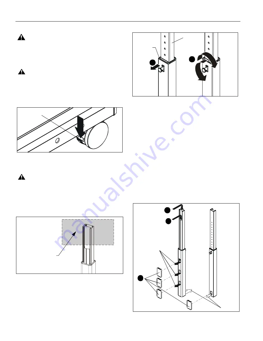
brakes on the back wheels by pressing down on the tab.
(See Figure 5)
1.
Attach accessory and component(s) to stand following
instructions included with the accessory.
Figure 5
Adjusting Stand Height
CAUTION:
ALWAYS remove components attached to
accessories BEFORE adjusting the height of stand.
1.
Firmly grasp
top
of
inner
column. (See Figure 6)
IMPORTANT ! :
Firmly grasp at the
top
of the
inner
column when adjusting stand height. (See Figure 6)
Figure 6
2.
Adjust the stand to the desired height by slightly lifting the
accessory, pulling out knob on the center post and turning
90
o
in either direction to disengage the locking mechanism.
(See Figure 7)
3.
Raise or lower the upright, then turn the knob 90
o
either
direction to engage the knob and lock the stand at desired
height. (See Figure 7)
Figure 7
IMPORTANT ! :
Set the height of the stand so the
accessories do NOT rest on the upper part of the outer column.
(See Figure 7) Always set the height so the knob is engaged in
a hole in the inner column.
Cable Management
1.
Signal cables can be run down the front flap of the upright
and out the front of the upright at any of the openings.
(See Figure 8)
2.
Any accessory power cords can be run through the front
and down through the upright to exit out the back. (See
Figure 8)
3.
Install the snap-on covers (C) to any opening that is not
being used. (See Figure 8)
4.
To remove the snap-on covers, grip the sides of the cover
in the middle and pull off. They can also be removed by
inserting a flat-blade screwdriver into the bottom slot and
rotating the screwdriver.
Figure 8
Press down to
set brakes
Grasp
top of inner
column (within shaded
area) when adjusting
stand height
Do NOT let
2
3
Inner
Column
accessory
rest here
2
(Rear view
of column)
(Front view
of column)
Exit for
power
cables
1
3
Exits for
signal cables
(C)


