background image

QMP1MM2

Installation Instructions

4

ASSEMBLY

The QMP1MM2 is designed to be attached to the inner column
of Chief carts and stands.
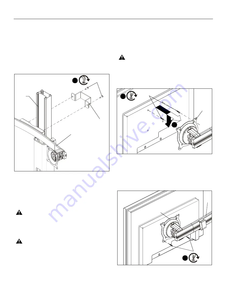
1.

Attach column to cart/stand base (not included) following
instructions included with cart/stand (not included).

2.

Fasten array clamp (B) around the cart/stand inner column
and to the dual array assembly (A) using two 1/4-20 x 3/4"
button head screws (H). (See Figure 1)

NOTE:

The QMP1MM2 attaches only to the

INNER

column of

the Chief cart or stand.

Figure 1

DISPLAY INSTALLATION

The mounting holes on the back of the displays will be

flush

with

 the back surface, or

recessed into

 the back. Refer to the

applicable installation procedure below.

Flush Display Installation

CAUTION:

IMPROPER INSTALLATION CAN LEAD TO

DISPLAY FALLING CAUSING SERIOUS PERSONAL
INJURY OR DAMAGE TO EQUIPMENT! Using screws of
improper size may damage your display!  Proper screws will
easily and completely thread into display mounting holes.

CAUTION:

IMPROPER INSTALLATION CAN LEAD TO

DISPLAY FALLING CAUSING SERIOUS PERSONAL
INJURY OR DAMAGE TO EQUIPMENT! Inadequate thread
engagement in display may cause display to fall!  Back out
screws ONLY as necessary to allow installation of Centris
cup!

1.

Ensure Centris cup is able to swivel and tilt easily, yet still
be tight enough to hold display in desired position.  Adjust
as required before proceeding.  See

Adjustment

section

for details.

2.

Carefully install two M4 x 12mm Phillips head cap screws
(E) into the

upper

 mounting holes on the display. Thread

screws completely into display, then back out 3 complete
turns.

3.

Align two screws (E) with the two top teardrop mounting
holes on the Centris cup and lower Centris cup onto
installed screws. (See Figure 2)

CAUTION:

IMPROPER INSTALLATION CAN LEAD TO

DISPLAY FALLING CAUSING SERIOUS PERSONAL
INJURY OR DAMAGE TO EQUIPMENT! Smaller area of
teardrop mounting holes must be facing downward for proper
installation. Reposition Centris cup if required.

Figure 2

4.

Install two M4 x 12mm Phillips head cap screws (E) through
the

lower

 mounting holes in Centris cup into the display.

(See Figure 3)

5.

Tighten all screws. Do not over tighten!

NOTE:

Repeat previous steps for the additional display.

Figure 3

6.

Proceed to

Cable Management

section.

2

(H) x 2

Cart/stand

(A)

(B)

column

inner

(E) x 2

3

2

(A)

(E) x 2

Centris Cup

4

(A)

Summary of Contents for QMP1MM2

Page 1: ...Instruções de Instalação Istruzioni di installazione Installatie instructies Instructions d installation Music Stand Dual Array Spanish Product Description German Product Description Portuguese Product Description Italian Product Description Dutch Product Description French Product Description QMP1MM2 ...

Page 2: ...f damage or destruction of equipment if you do not follow the corresponding instructions WARNING Failure to read thoroughly understand and follow all instructions can result in serious personal injury damage to equipment or voiding of factory warranty It is the installer s responsibility to make sure all components are properly assembled and installed using the instructions provided WARNING Failur...

Page 3: ...ssaggio Bevestiging losdraaien Desserrez les fixations Phillips Screwdriver Destornillador Phillips Kreuzschlitzschraubendreher Chave de fendas Phillips Cacciavite a stella Kruiskopschroevendraaier Tournevis à pointe cruciforme Hex Head Wrench Llave de cabeza hexagonal Sechskantschlüssel Chave de cabeça sextavada Chiave esagonale Zeskantsleutel Clé à tête hexagonale 2 5 32 included A 1 Dual array ...

Page 4: ...QUIPMENT Inadequate thread engagement in display may cause display to fall Back out screws ONLY as necessary to allow installation of Centris cup 1 Ensure Centris cup is able to swivel and tilt easily yet still be tight enough to hold display in desired position Adjust as required before proceeding See Adjustment section for details 2 Carefully install two M4 x 12mm Phillips head cap screws E into...

Page 5: ...cers F or G rotate the Centris cup as required See Figure 6 CAUTION IMPROPER INSTALLATION CAN LEAD TO DISPLAY FALLING CAUSING SERIOUS PERSONAL INJURY OR DAMAGE TO EQUIPMENT Using screws of improper size may damage your display Proper screws will easily and completely thread into display mounting holes 8 Install four M4 x 20mm D or four M4 x 30mm C Phillips head cap screws through the mounting hole...

Page 6: ...1 Using your fingers slightly loosen horizontal adjustment knob See Figure 10 2 Slide display along array to desired position 3 Using your fingers tighten horizontal adjustment knob See Figure 10 Pitch Yaw Roll Tension 1 Using your fingers slightly loosen tension knob See Figure 10 2 Adjust display as desired 3 Using your fingers tighten tension knob Figure 10 Cart Stand Adjustment Follow adjustme...

Page 7: ...Installation Instructions QMP1MM2 7 ...

Page 8: ...03 DK Weert Netherlands P 31 0 495 580 852 F 31 0 495 580 845 Asia Pacific A Office No 918 on 9 F Shatin Galleria 18 24 Shan Mei Street Fotan Shatin Hong Kong P 852 2145 4099 F 852 2145 4477 QMP1MM2 Installation Instructions Chief a products division of Milestone AV Technologies 8800 002933 Rev00 2016 Milestone AV Technologies www milestone com 12 16 ...

Reviews: