Installation Instructions
SL151i
5
INSTALLATION REQUIREMENTS
The SL151i has been designed to be mounted either recessed
into a ceiling, or flush-mounted in a finished ceiling.
Power Requirements
•
230VAC, 50Hz, 2 amps (if NOT installing an
internal outlet for projector).
•
230VAC, 50Hz, 12 amps (if installing an
internal outlet [not provided] for projector).
IMPORTANT ! :
Installation and maintenance of this product
must be completed by a qualified service technician.
Pre-Test Lift before Installation
1.
Carefully inspect the SL151i for any shipping damage. If
any damage is apparent, do NOT continue with the
installation. Instead, contact Chief for further instructions.
2.
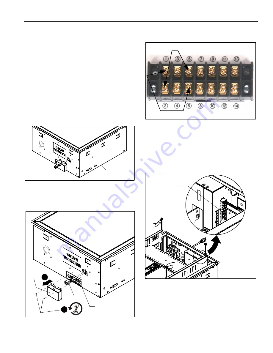
Place SL151i upside down on clean surface. (See Figure 1)
Figure 1
3.
Remove and save two screws holding side electrical cover
in place. (See Figure 2)
4.
Remove electrical cover. (See Figure 2)
Figure 2
5.
Place the jumper wire (H) on the external wiring terminal
contacts labeled
2
and
5
, and wire the push button
assembly (D) to contacts
1 (red)
and
6 (black)
. (See
Figure 3).
Figure 3
6.
Plug the SL151i test inlet in using the supplied test power
cord (J).
NOTE:
The supplied test power cord (J) may not work in all
countries, and the user may need to supply an
appropriate cord for the country of use.
NOTE:
(See Figure 2) for location of external wiring terminal.
(See Figure 4) for location of internal wiring terminal.
Figure 4
Power Requirements and Wiring
The SL151i requires 230VAC, 50 Hz and 2 amps power to
operate.
NOTE:
A 6 ft. long power cord is provided with the mount. This
supplied power cord should be used for testing only,
and not for the permanent installation. (The SL151i will
be hard-wired at installation.)
SL151i top
x 2
3
Electrical
Cover
4
Test inlet
External
wiring terminal
Place jumper wire (H) (2 and 5)
Wire push button assembly (D) (
1
-red,
6
-black)
[Some parts not
shown for clarity]
Internal
wiring terminal
Summary of Contents for SMART-LIFT SL151i
Page 11: ...Installation Instructions SL151i 11 Table 2 INTERNAL TERMINAL DESCRIPTIONS ...
Page 12: ...SL151i Installation Instructions 12 Figure 17 ...
Page 14: ...SL151i Installation Instructions 14 ...
Page 25: ...Instrucciones de instalación SL151i 25 Tabla 2 DESCRIPCIÓN DEL BLOQUE DE TERMINALES INTERNO ...
Page 26: ...SL151i Instrucciones de instalación 26 Figura 17 ...


