background image

Installation Instructions

SL236i

7

Figure 4

Power Requirements and Wiring

The SL236i requires 230VAC 50 Hz power to operate.

NOTE:

A 6 ft. long power cable is provided with the mount.

This supplied power cord should be used for testing
only, and not for the permanent installation.
(The SL236i will be hard-wired at installation.)

IMPORTANT ! :

This product must be grounded. If it should

malfunction or break down, grounding provides a path of least
resistance for electric current to reduce the risk of electric
shock.

Grounding Instructions

This product is equipped with a test cord having an equipment-
grounding conductor and a grounding plug. The plug must be
plugged into an appropriate outlet that is properly installed and
grounded in accordance with all local codes and ordinances.

WARNING:

RISK OF ELECTROCUTION! All electrical

wiring required for installation should be installed by a
qualified electrician.

WARNING:

PINCH HAZARD! FINGERS OR HANDS

BETWEEN MOVING PARTS CAN LEAD TO SEVERE
PERSONAL INJURY! Keep fingers and hands away from
mount when operating.

8.

Press the push button (B) to test the SL236i while it is still in
the pre-test position.

Press when the lift is at its top position and it will move
down.

Press when the lift is at its bottom position and it will
move up.

Press while the lift is moving and it will stop.

Leave SL236i in the closed position.

INSTALLING IN CEILING

WARNING:

IMPROPER INSTALLATION CAN LEAD TO

LIFT FALLING CAUSING SEVERE PERSONAL INJURY OR
DAMAGE TO EQUIPMENT! It is the installers responsibility
to make certain the structure to which the lift is being
mounted is capable of supporting five times the weight of the
lift and all attached equipment. Reinforce the structure as
required before installing the lift.

NOTE:

The following instructions assume a suitable mounting

structure and surface exists prior to installation and all
power and signal wires and cables have been properly
installed.

Installing in a Suspended Ceiling (SL236SPi)

NOTE:

The SL236SPi may be suspended from three 3/8 in.

diameter x 8 in. length (minimum) Grade 2 or better
threaded rods (not provided) which are secured to a
1-5/8" x 1-5/8" 12 ga metal framing channel (spanning
a maximum of 5 feet--not provided) by Grade 2 or
better 3/8" channel nuts (not provided).

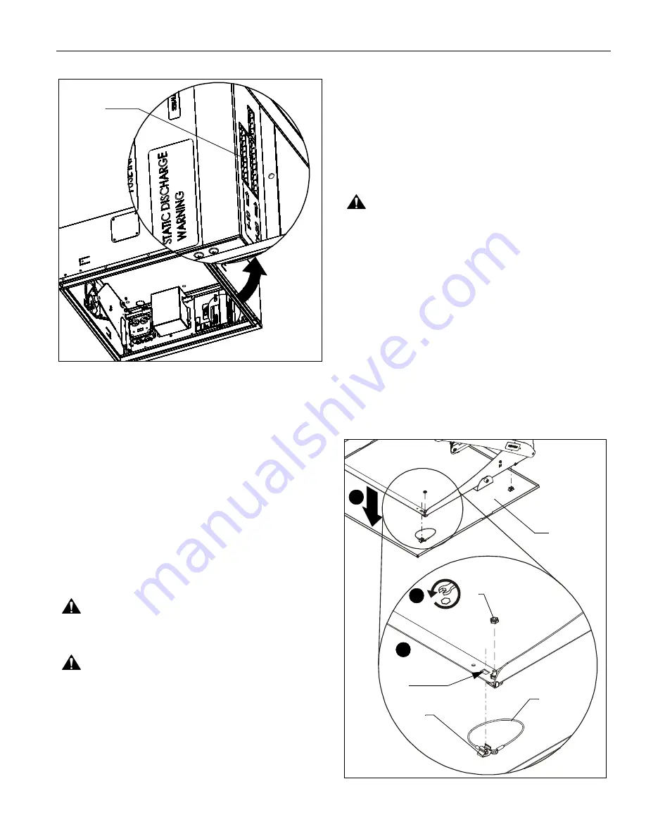
1.

Remove and save nuts attaching guide wires to two corners
of ceiling panel. (See Figure 5)

Figure 5

[Some parts not
shown for clarity]

Internal
wiring terminal

x 2

Ceiling
Panel

Clip

1

Remove
clip from
hole

2

2

Guide
wire

Summary of Contents for SMART-LIFT SL236i

Page 1: ...erference in a residential installation This equipment generates uses and can radiate radio frequency energy and if not installed and used in accordance with the instructions may cause harmful interference to radio or television communications However there is no guarantee that the interference will not occur in a particular installation If this equipment does cause harmful interference to radio o...

Page 2: ...CTRIC SHOCK OR INJURY TO PERSONS Always turn off power at source before putting on or taking off parts Use this mounting system only for its intended use as described in these instructions Do NOT use attachments not recommended by the manufacturer Never operate this mounting system if it has a damaged test cord or test plug If it is not working properly during testing return the mounting system to...

Page 3: ...TOOLS REQUIRED FOR INSTALLATION PARTS I M x1 A 1 B 1 C 5 D 1 E 1 F 5 G 4 6 32 x 3 16 H 2 Ceiling lift Push button assembly 4 cable tie Cable tie mount External terminal cover plate Rubber grommet Jumper wire SL236FDi Shown J 1 Power cord ...

Page 4: ...2 Plenum Rated Installation 12 Wiring Options 12 Table 1 Wiring Table 13 Table 2 Internal Terminal Descriptions 14 Internal External Wiring Terminal Descriptions 15 Phillips Screwdriver Destornillador Phillips Kreuzschlitzschraubendreher Chave de fendas Phillips Cacciavite a stella Kruiskopschroevendraaier Tournevis à pointe cruciforme Adjust Ajustar Einstellen Ajustar Regolare Afstellen Ajuster T...

Page 5: ...INCHES 606 6 CURRENT 9 26 235 2 MAX 9 91 251 7 MIN 7 78 197 6 25 12 700 0 719 1 4 34 3 00 23 00 20 50 10 25 12 25 11 12 65 16 5 1 06 26 9 24 94 23 88 36 00 MAX 1 07 27 2 41 10 4 MAXIMUM AVAILABLE SPACE FOR PROJECTOR AND EQUIPMENT HxWxD 9 25 x 20 50 x 22 75 INCHES 520 7 76 2 260 4 584 2 638 0 110 2 27 56 28 31 23 88 REMEMBER TO ADD 375 TO 1 00 9 5 TO 25 4mm TO THE MAX 9 91 251 7mm OF YOUR PROJECTOR...

Page 6: ...further instructions 2 Attach supports not provided to the top of lift See Figure 1 Figure 1 3 Suspend the lift at least 3 1 2 ft above a surface from a suitable structure such as saw horses ladders or tables 4 Remove and save two screws holding side electrical cover in place See Figure 2 5 Remove electrical cover See Figure 2 Figure 2 6 Place the jumper wire E on the external wiring terminal cont...

Page 7: ...tion Press when the lift is at its top position and it will move down Press when the lift is at its bottom position and it will move up Press while the lift is moving and it will stop Leave SL236i in the closed position INSTALLING IN CEILING WARNING IMPROPER INSTALLATION CAN LEAD TO LIFT FALLING CAUSING SEVERE PERSONAL INJURY OR DAMAGE TO EQUIPMENT It is the installers responsibility to make certa...

Page 8: ...onal accessory to the SL236SPi if applicable following instructions included with the kit 8 Insert the ceiling grid edge surrounding the SL236SPi into the side channel of the SL236SPi See Figure 7 NOTE The side channel of the lift will support the weight of the grid and ceiling tiles Figure 7 CAUTION The lift MUST be installed square and parallel Avoid stressing or bending the lift during installa...

Page 9: ...crews not provided to secure SL236FDi to the joists or wood framework using the mounting tabs located on the sides of the SL236FDi housing See Figure 10 NOTE There are three mounting tabs on each side and two mounting tabs on the front of the SL236FDi There are three mounting holes in the back of the SL236FDi The SL236FDi must be installed using the back mounting holes AND the front two mounting t...

Page 10: ...ch end of yaw adjustment bracket See Figure 12 Figure 12 Adjustments 1 TRAVEL SHOW ADJUSTMENT CAUTION Do not overadjust exceed maximum travel length To adjust the travel of the lift mechanism insert a Phillips screwdriver into the access hole found at the left rear corner of the lift NOTE The access hole may be covered by ceiling tile in the SL236SPi model Shorten travel by turning adjustment scre...

Page 11: ... or down in the side holes on one side or the other by loosening nuts Adjust and tighten nuts on bracket See Figure 16 Figure 16 Routing Cables CAUTION Do NOT attach cables to lower lifting arms or sides of projector bracket Damage may result when lift is raised 1 Lower SL236i to service position 2 Route and secure electrical and video cables using installed cable clips See Figure 17 Remove nut an...

Page 12: ...i is cycled up and down repeatedly the motor s thermal overload protection will stop operation Operation will resume when the thermal overload resets usually within 3 to 5 minutes Connecting to Power Supply Plenum Rated Installation 1 Disconnect and remove power inlet from interior junction box 2 Hardwire unit to a 230V 50 Hz 2 amp power source NOTE This unit was designed to have conduit run direc...

Page 13: ...3 Table 1 WIRING TABLE Figure 18 NOTE The numbers listed in the SL236i Internal and SL236i External columns refer to the corresponding numbers located where indicated in the wiring pictures See Figure 18 EXTERNAL WIRING INTERNAL WIRING ...

Page 14: ...SL236i Installation Instructions 14 Table 2 INTERNAL TERMINAL DESCRIPTIONS ...

Page 15: ...Installation Instructions SL236i 15 Figure 19 ...

Page 16: ...SL236i Installation Instructions 16 ...

Page 17: ...Installation Instructions SL236i 17 ...

Page 18: ...SL236i Installation Instructions 18 ...

Page 19: ...Installation Instructions SL236i 19 ...

Page 20: ... Company www chiefmfg com 05 11 USA International A 8401 Eagle Creek Parkway Savage MN 55378 P 800 582 6480 952 894 6280 F 877 894 6918 952 894 6918 Europe A Fellenoord 130 5611 ZB EINDHOVEN The Netherlands P 31 0 40 2668620 F 31 0 40 2668615 Asia Pacific A Office No 1 on 12 F Shatin Galleria 18 24 Shan Mei Street Fotan Shatin Hong Kong P 852 2145 4099 F 852 2145 4477 ...

Reviews: