Installation Instructions
TA500
7
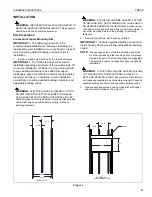
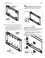
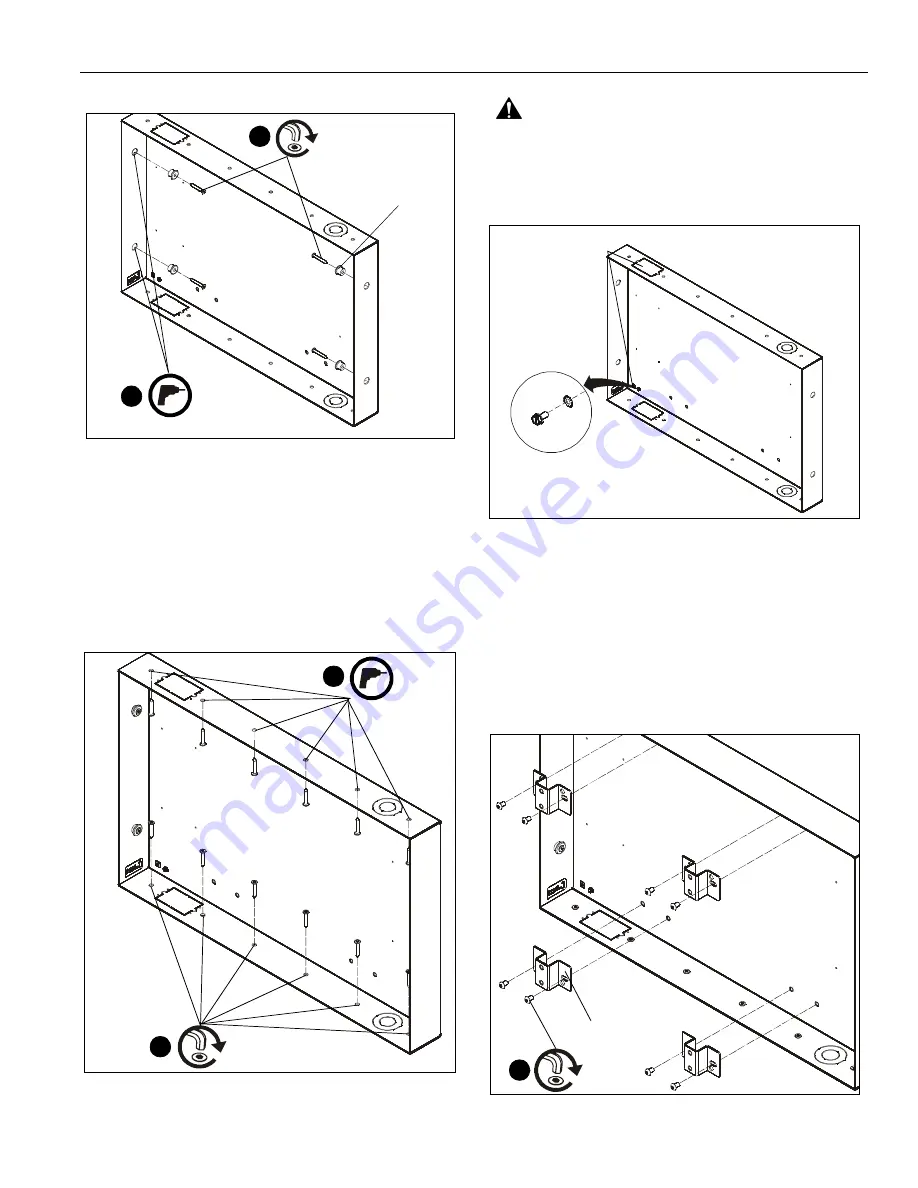
Figure 4
NOTE:
The TA500 has 1/2” total clearance between the two
studs. The spacers allow side to side adjustment.
7.
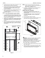
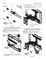
Drill eight 3/16” diameter pilot holes in horizontal framing at
top and bottom mounting holes. (See Figure 5)
8.
Attach the TA500 (A) to horizontal framing using twelve
M7 x 40mm Allen head connector screws (C) using an M4
Allen head drill bit (F). (See Figure 5)
Figure 5
DANGER:
IMPROPER WIRING CAN LEAD TO DEATH
OR SEVERE PERSONAL INJURY! Grounding must be
installed by qualified personnel using a UL Recognized No.
12AWG grounding wire connected to grounding lug on
mount.
Figure 6
TS325TU/TS525TU Installation
IMPORTANT ! :
The TA500 was designed specifically for
the TS325TU or TS525TU wall mount. Do not attempt to
install any other wall mounts with the TA500!
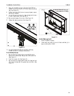
1.
Use eight 5/16-18 x 1/2” button head cap screws (M) to
attach four attachment brackets (N) to the TA500 (A). (See
Figure 7) and (See Figure 8)
IMPORTANT ! :
Bracket orientation is different
depending on mount being installed.
Figure 7
x
5
6
x 4
(D) x 4
(B) x 4
8
(C) x 12
7
x 12
Grounding Lug Locations
1
(M) x 8
(N) x 4
(TS325TU)


