TA500
Installation Instructions
8
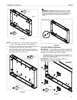
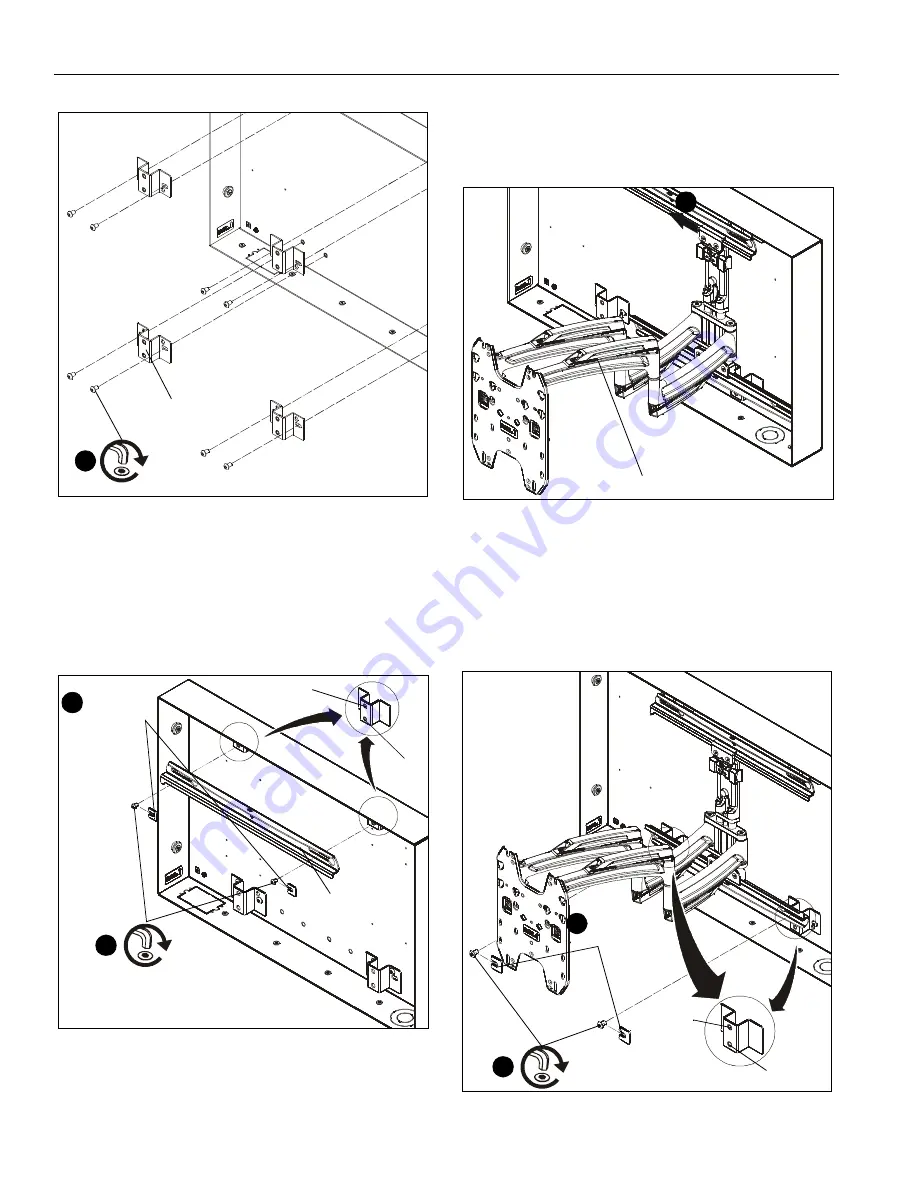
Figure 8
2.
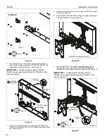
Use two 5/16-18 x 1/2” button head cap screws (M) to
loosely attach upper wall plate of TS325TU/TS525TU to
upper attachment brackets (N). (See Figure 9)
IMPORTANT ! :
Install to upper bracket holes for
TS525TU and lower bracket holes for TS325TU. See
Inset on Figure 9.
Figure 9
3.
Place two installation spacers (included with TS325TU/
TS525TU) over two 5/16-18 x 1/2” button head cap screws
(M). (See Figure 9)
4.
Tighten two screws (M) to secure upper wall plate to upper
attachment brackets.
5.
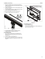
Slide TS325TU/TS525TU assembly onto upper wall plate of
TS325TU/TS525TU. (See Figure 10)
Figure 10
6.
Use two 5/16-18 x 1/2” button head cap screws (M) to
loosely attach lower wall plate of TS325TU/TS525TU
assembly to lower attachment brackets (N). (See Figure 11)
IMPORTANT ! :
Install to lower bracket holes for
TS525TU and upper bracket holes for TS325TU. See
inset on Figure 11.
Figure 11
(TS525TU)
1
(M) x 8
(N) x 4
TS325TU upper
2
(M) x 2
installation
spacers x 2
4
wall plate
TS525TU
TS325TU
5
TS325TU assembly shown
6
(M) x 2
installation
spacers x 2
7
TS325TU
TS525TU


