Installation Instructions
TA500
9
7.
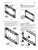
Place two installation spacers (included with TS325TU/
TS525TU) over two 5/16-18 x 1/2” button head cap screws
(M). (See Figure 11)
8.
Tighten two screws (M) to secure lower wall plate to lower
attachment brackets.
9.
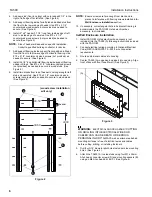
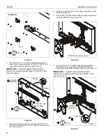
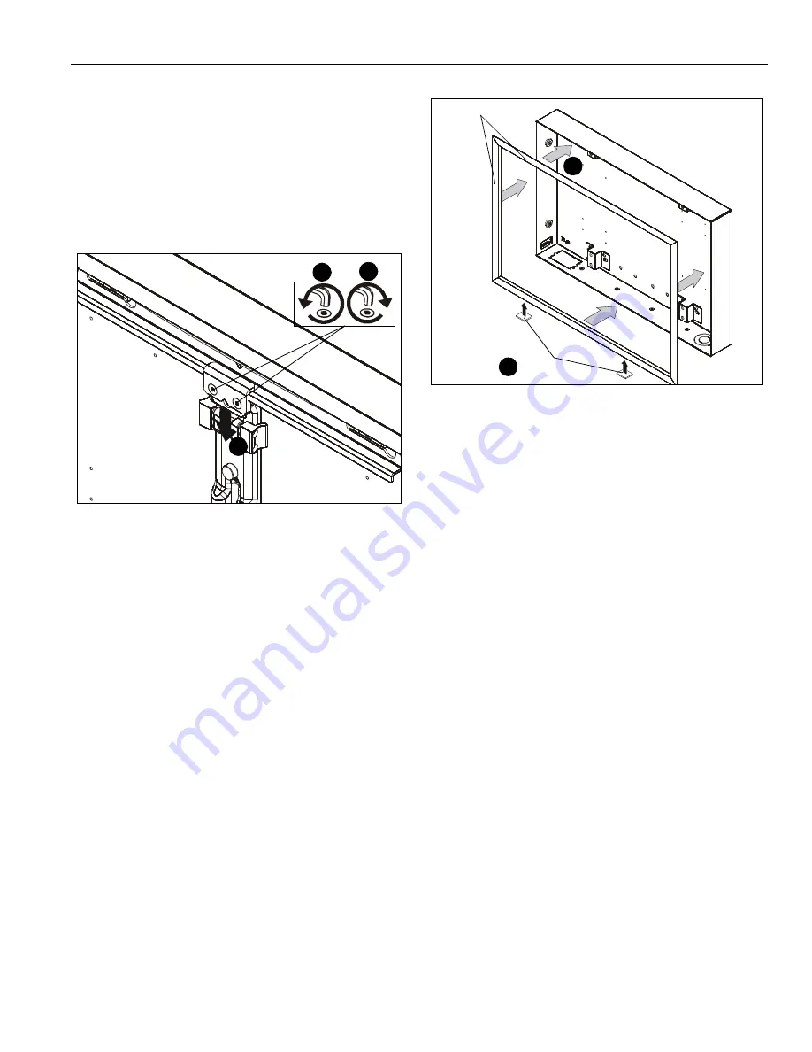
Loosen flat head cap screws on upper carriage rail in order
to loosen white spacer. (See Figure 12)
10. Remove white spacer from mount. (See Figure 12)
11. Tighten flat head cap screws. (See Figure 12)
Figure 12
12. Complete TS325TU/TS525TU installation following
TS325TU/TS525TU installation instructions.
Trim Kit (Optional)
1.
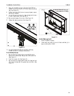
Remove paper covering adhesive and affix three tape
squares (K) to inside lower flange of each trim piece (G).
(See Figure 13)
2.
Orient trim pieces (G). (See Figure 13)
3.
Remove paper covering adhesive back from tape squares
(K) on trim and press trim (G) against inner wall of box. (See
Figure 13)
Figure 13
Cable Management
1.
Attach all cables to display.
2.
If necessary, use cable tie mounts (H) and cable ties (J) to
secure cables within TA500.
9
11
10
(G) x 4
3
(K) x 16
1
(TS325TU/TS525TU mount
not shown for clarity)


