4
2
、
Units operating working conditions and temperature range
2 . 1
Rated conditions
The Standard condition is in accordance with ANSI/AHAM RAC-1-2003, and UL
484.
Cooling:
Indoor: 80
o
FDB 67
o
F WB
Outdoor: 95
o
F DB 75
o
F WB
Heating:
Indoor: 70
o
F DB 60
o
F WB
Outdoor: 47
o
F DB 43
o
F WB
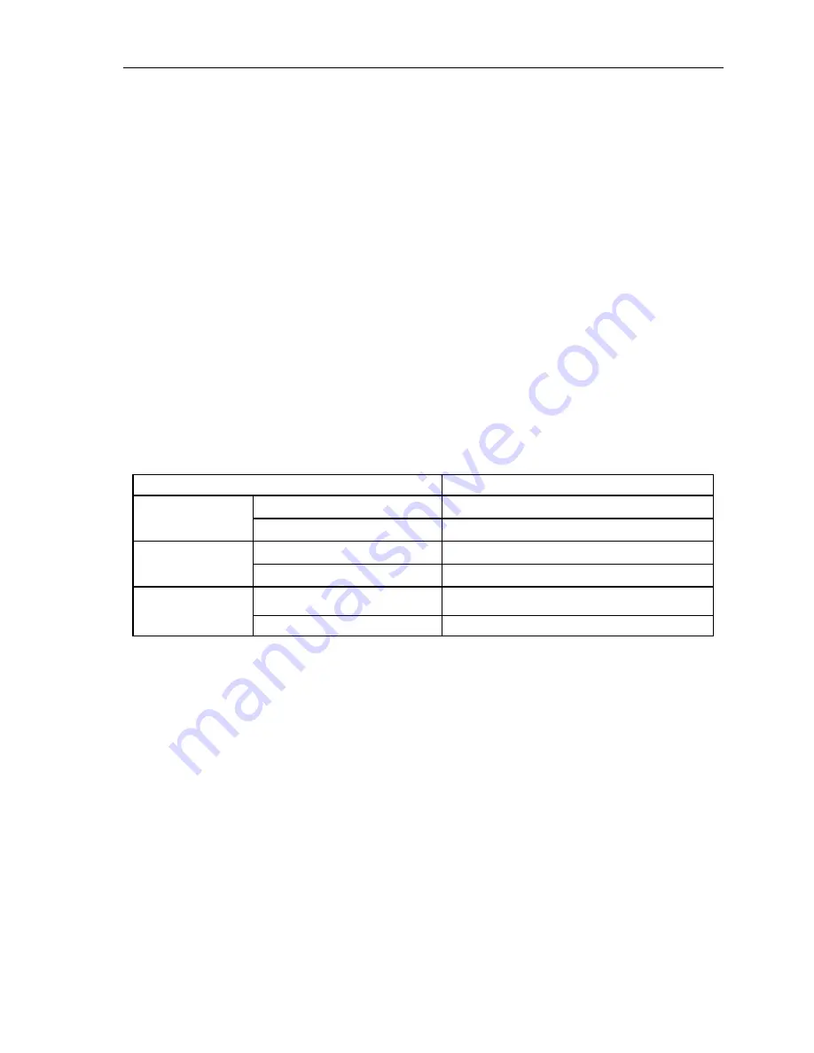
2 . 2 O p e r a t i n g
L i m i t s
Outdoor
Upper limit (DB)
110
o
F
Cooling
Lower limit (DB)
5
o
F
Upper limit (DB)
75
o
F
Heating
Lower limit (DB)
5
o
F
2PH 198–264V/115V
Voltage
3PH N/A
Summary of Contents for CS-25V1A-H1; CS-35V1A-E2; CS-50V9A-S; CS-70V9A-T
Page 1: ...DC Inverter Split Air Condition Unit SERVICE MANUAL ...
Page 3: ...3 1 Air conditioning unit parameters ...
Page 6: ...6 ...
Page 8: ...8 The curve diagram of the compressor condensing pressure ...
Page 12: ...12 Capacity Correction Factor Due to Tubing Length One Way Cooling Heating ...
Page 13: ...13 Pressure Curve Suction Pressure Curve Discharge Pressure Curve ...
Page 15: ...15 4 Indoor and outdoor units size 4 1 outdoor Unit CS 25V1A H1 4 2 outdoor Unit CS 35V1A E2 ...
Page 16: ...16 4 3 outdoor Unit CS 50V9A S 4 4 outdoor Unit CS 70V9A T ...
Page 19: ...19 ...
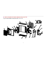
Page 20: ...20 5 2 The explosion diagram and spare parts list for CS 25V1A M81A ON OFF ...
Page 21: ...21 ...
Page 22: ...22 5 3 The explosion diagram and spare parts list for CS 35V1A E2 ...
Page 23: ...23 ...
Page 24: ...24 5 4 The explosion diagram and spare parts list for CS 35V1A P81A ON 0FF F ...
Page 25: ...25 ...
Page 26: ...26 5 5 The explosion diagram and spare parts list for CS 50V9A S ...
Page 27: ...27 ...
Page 28: ...28 5 6 The explosion diagram and spare parts list for CS 50V9A S81A ON 0FF F ...
Page 29: ...29 ...
Page 30: ...30 5 7 The explosion diagram and spare parts list for CS 70V9A T ...
Page 31: ...31 ...
Page 32: ...32 5 8 The explosion diagram and spare parts list for CS 50V9A S ...
Page 33: ...33 ...


