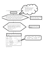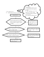
5,Malfunction code
:
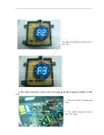
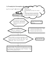
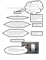
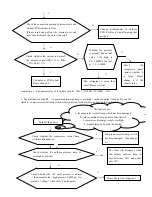
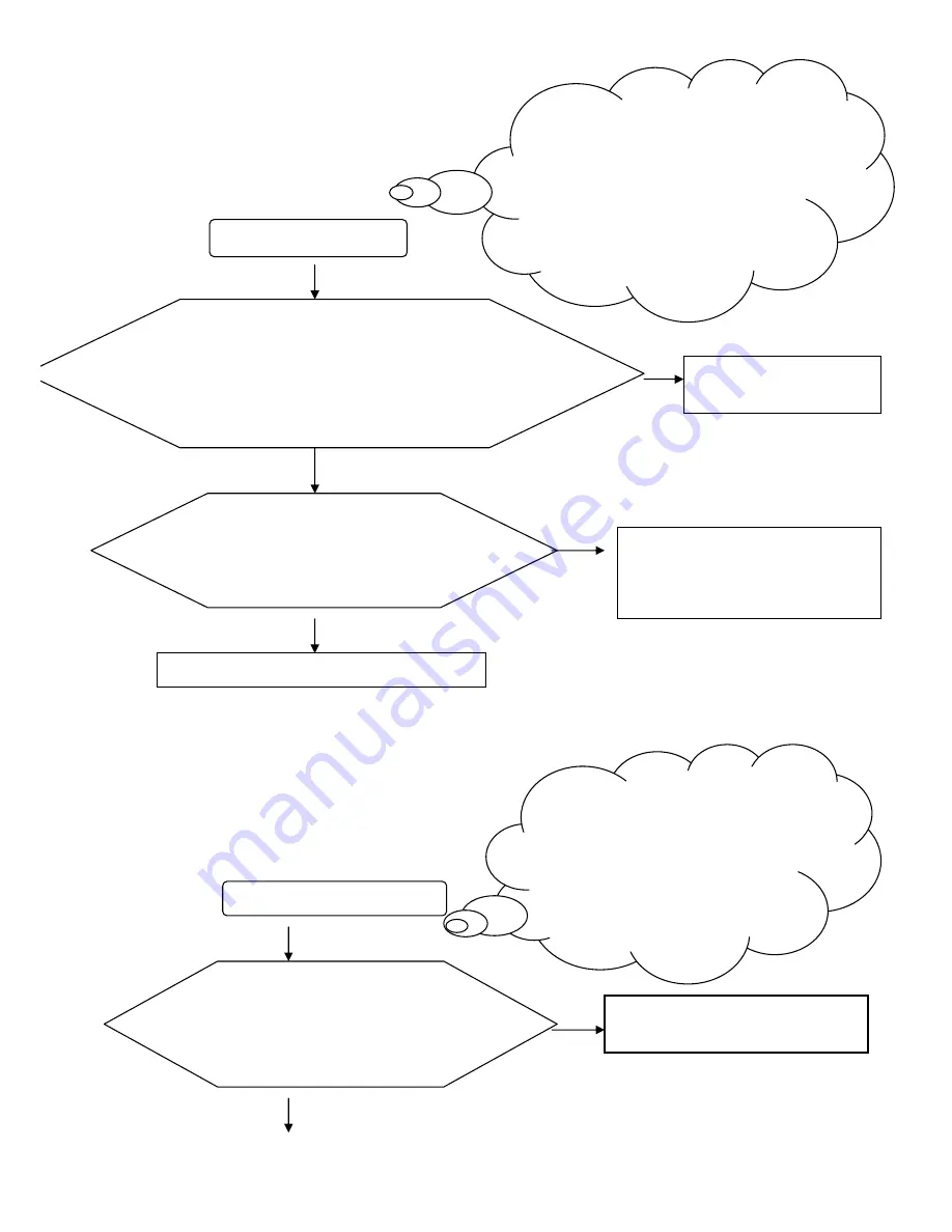
F6
(
the outdoor temp sensor fault
)
6,Malfunction code
:
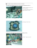
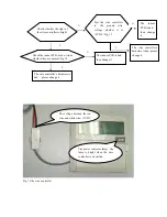
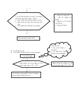
FA
(
the communication fault between the wire controller to the indoor PCB
)
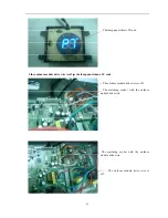
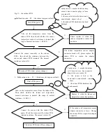
Turn off the power
Take out the temperature sensor from outdoor PCB. Then test
this outdoor temperature sensor resistance whether ii is normal
(the normal: discharge sensor is 3K~200K the other sensor is
1K~40K).
N
The outdoor temp sensor is
bad, Please change it.
Y
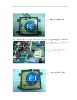
Connect the sensor with the indoor PCB again.
Check the sensor and the indoor PCB terminal
resistance. The normal value is 0
Ω
N
The indoor temperature sensor adapter
connector is loose. Change this indoor
PCB or repair this adapter connector
Y
The indoor PCB is bad. Please change it
Electrify and turn on the unit
Check the connecting line
、
wire controller
、
PCB whether they are loose or have a bad
contact.
Y
Please change the connecting line or
repair the loose terminal
N
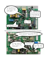
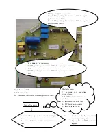
Faulty cause
:
1
、
maybe the indoor coil
temp sensor’s BNC connector plugs is
loose or contact ill;
2
、
the sensor is bad or the down-lead is
circuit-break
、
circuit
-
short
3
、
the indoor PCB’s hardware has been
damaged
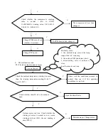
The faulty cause
:
1
、
the wire controller’s connecting plug
is loose or contacts ill
2
、
the wire controller’s hardware has
been damaged ;
3
、
the indoor PCB has been damaged.
Summary of Contents for CS-25V1A-H1; CS-35V1A-E2; CS-50V9A-S; CS-70V9A-T
Page 1: ...DC Inverter Split Air Condition Unit SERVICE MANUAL ...
Page 3: ...3 1 Air conditioning unit parameters ...
Page 6: ...6 ...
Page 8: ...8 The curve diagram of the compressor condensing pressure ...
Page 12: ...12 Capacity Correction Factor Due to Tubing Length One Way Cooling Heating ...
Page 13: ...13 Pressure Curve Suction Pressure Curve Discharge Pressure Curve ...
Page 15: ...15 4 Indoor and outdoor units size 4 1 outdoor Unit CS 25V1A H1 4 2 outdoor Unit CS 35V1A E2 ...
Page 16: ...16 4 3 outdoor Unit CS 50V9A S 4 4 outdoor Unit CS 70V9A T ...
Page 19: ...19 ...
Page 20: ...20 5 2 The explosion diagram and spare parts list for CS 25V1A M81A ON OFF ...
Page 21: ...21 ...
Page 22: ...22 5 3 The explosion diagram and spare parts list for CS 35V1A E2 ...
Page 23: ...23 ...
Page 24: ...24 5 4 The explosion diagram and spare parts list for CS 35V1A P81A ON 0FF F ...
Page 25: ...25 ...
Page 26: ...26 5 5 The explosion diagram and spare parts list for CS 50V9A S ...
Page 27: ...27 ...
Page 28: ...28 5 6 The explosion diagram and spare parts list for CS 50V9A S81A ON 0FF F ...
Page 29: ...29 ...
Page 30: ...30 5 7 The explosion diagram and spare parts list for CS 70V9A T ...
Page 31: ...31 ...
Page 32: ...32 5 8 The explosion diagram and spare parts list for CS 50V9A S ...
Page 33: ...33 ...

