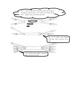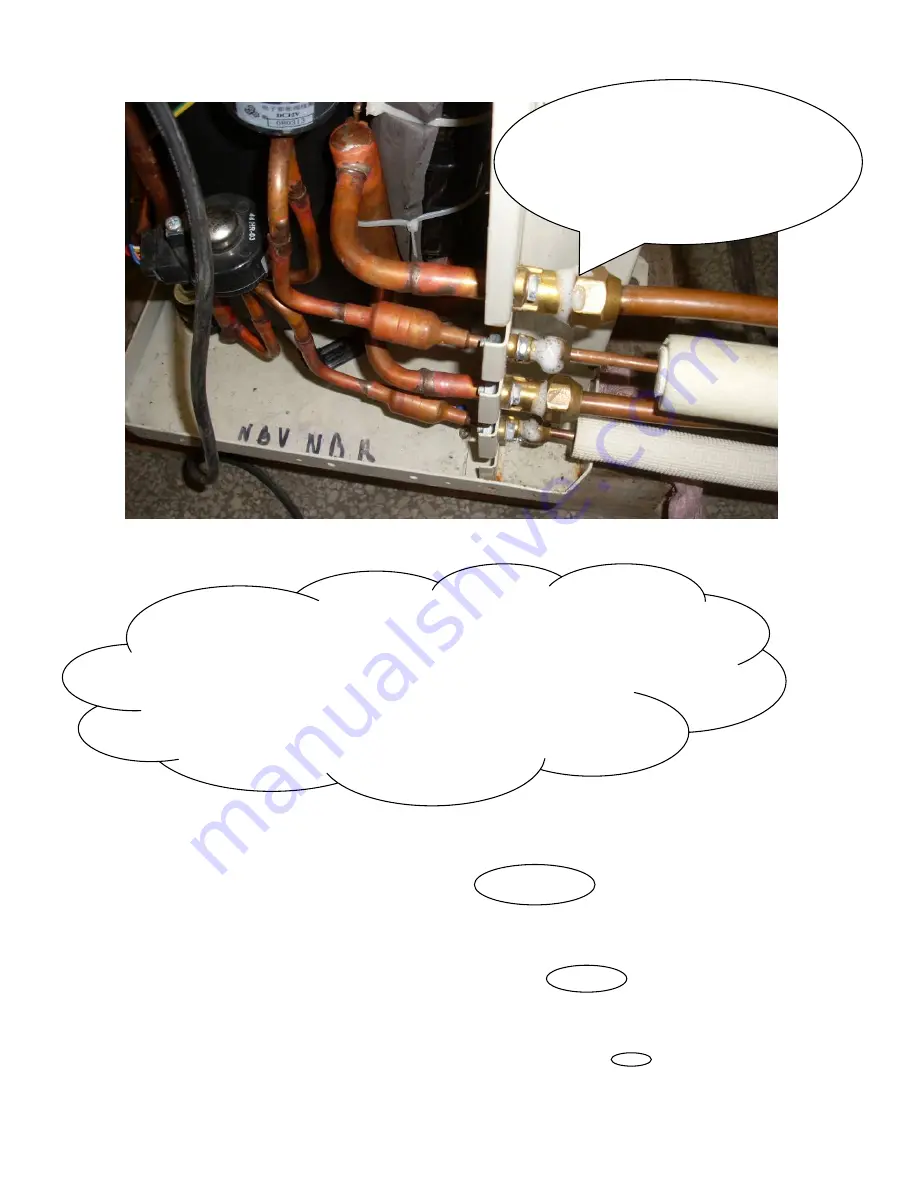
Fig. 16
、
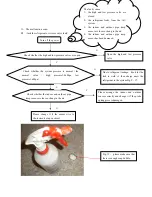
Please daub the bubble to four
terminals, then observe them for five
minutes! If there are some bubbles that
grow slowly and broke around the
terminal,. it shows the leakage
Warning
:
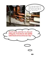
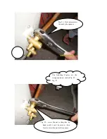
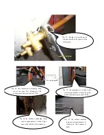
please connecting the indoor and
outdoor units according to the correct installing
method
,
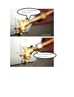
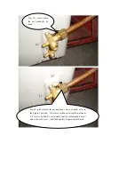
Fig. 17~21 show the right operating
way
;(
Note
:
the indicator figures aren’t the real
photos about the DC inverter dual zone unit
)
Summary of Contents for CS-25V1A-H1; CS-35V1A-E2; CS-50V9A-S; CS-70V9A-T
Page 1: ...DC Inverter Split Air Condition Unit SERVICE MANUAL ...
Page 3: ...3 1 Air conditioning unit parameters ...
Page 6: ...6 ...
Page 8: ...8 The curve diagram of the compressor condensing pressure ...
Page 12: ...12 Capacity Correction Factor Due to Tubing Length One Way Cooling Heating ...
Page 13: ...13 Pressure Curve Suction Pressure Curve Discharge Pressure Curve ...
Page 15: ...15 4 Indoor and outdoor units size 4 1 outdoor Unit CS 25V1A H1 4 2 outdoor Unit CS 35V1A E2 ...
Page 16: ...16 4 3 outdoor Unit CS 50V9A S 4 4 outdoor Unit CS 70V9A T ...
Page 19: ...19 ...
Page 20: ...20 5 2 The explosion diagram and spare parts list for CS 25V1A M81A ON OFF ...
Page 21: ...21 ...
Page 22: ...22 5 3 The explosion diagram and spare parts list for CS 35V1A E2 ...
Page 23: ...23 ...
Page 24: ...24 5 4 The explosion diagram and spare parts list for CS 35V1A P81A ON 0FF F ...
Page 25: ...25 ...
Page 26: ...26 5 5 The explosion diagram and spare parts list for CS 50V9A S ...
Page 27: ...27 ...
Page 28: ...28 5 6 The explosion diagram and spare parts list for CS 50V9A S81A ON 0FF F ...
Page 29: ...29 ...
Page 30: ...30 5 7 The explosion diagram and spare parts list for CS 70V9A T ...
Page 31: ...31 ...
Page 32: ...32 5 8 The explosion diagram and spare parts list for CS 50V9A S ...
Page 33: ...33 ...

