9
Cooling Capacity (BTU)---Run Model,230/115V,Indoor fan at high speed
INDOOR ENTERING AIR DB/WB TEMPERATURE [
0
F]
OUTDOOR
ENTERING AIR DB
TEMPERATURE[
0
F]
DATA 72/59 75/63 81/66 84/70 90/73
TC
80 - 110 % of nominal
SC
80 - 105 % of nominal
14~68
(protection range)
PI
25 - 50 % of nominal
TC
11616 12336 13104 13872 14640
SC 10421
10603
10845
11027
11269
77
PI 0.72 0.73 0.75 0.76 0.77
TC 11040
11808
12576
13296
14064
SC
10118 10361 10542 10785 10966
86
PI 0.81 0.82 0.83 0.85 0.86
TC 10464
11232
12000
12768
13536
SC
9876 10058 10300 10542 10724
95
PI 0.88 0.90 0.92 0.93 0.94
TC
9936 10704 11424 12192 12960
SC 9634
9815
10058
10239
10482
104
PI 0.97 0.98 0.99 1.01 1.02
TC 9264
10032
10752
11520
12288
SC 9270 9512 9694 9936 10118
115
PI 1.07
1.08
1.09
1.11
1.13
L E G E N D
TC – Total Cooling Capacity, BTU SC – Sensible Capacity, BTU PI – Power Input, kW
WB – Wet Bulb Temp., (
0
F
) DB – Dry Bulb Temp., (
0
F
) ID – Indoor OD – Outdoor
Summary of Contents for CS-25V1A-H1; CS-35V1A-E2; CS-50V9A-S; CS-70V9A-T
Page 1: ...DC Inverter Split Air Condition Unit SERVICE MANUAL ...
Page 3: ...3 1 Air conditioning unit parameters ...
Page 6: ...6 ...
Page 8: ...8 The curve diagram of the compressor condensing pressure ...
Page 12: ...12 Capacity Correction Factor Due to Tubing Length One Way Cooling Heating ...
Page 13: ...13 Pressure Curve Suction Pressure Curve Discharge Pressure Curve ...
Page 15: ...15 4 Indoor and outdoor units size 4 1 outdoor Unit CS 25V1A H1 4 2 outdoor Unit CS 35V1A E2 ...
Page 16: ...16 4 3 outdoor Unit CS 50V9A S 4 4 outdoor Unit CS 70V9A T ...
Page 19: ...19 ...
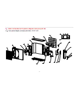
Page 20: ...20 5 2 The explosion diagram and spare parts list for CS 25V1A M81A ON OFF ...
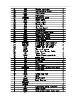
Page 21: ...21 ...
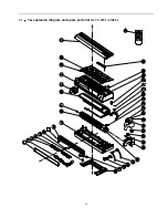
Page 22: ...22 5 3 The explosion diagram and spare parts list for CS 35V1A E2 ...
Page 23: ...23 ...
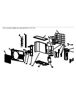
Page 24: ...24 5 4 The explosion diagram and spare parts list for CS 35V1A P81A ON 0FF F ...
Page 25: ...25 ...
Page 26: ...26 5 5 The explosion diagram and spare parts list for CS 50V9A S ...
Page 27: ...27 ...
Page 28: ...28 5 6 The explosion diagram and spare parts list for CS 50V9A S81A ON 0FF F ...
Page 29: ...29 ...
Page 30: ...30 5 7 The explosion diagram and spare parts list for CS 70V9A T ...
Page 31: ...31 ...
Page 32: ...32 5 8 The explosion diagram and spare parts list for CS 50V9A S ...
Page 33: ...33 ...


