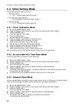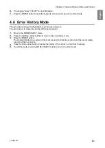
Chapter 5
Maintenance and Checkup
CMN209-004
55
E
ng
lis
h
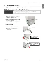
5.1.3
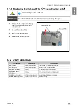
Replacing the Exhaust Filter
(
-V1 specification only
)
CAUTION
Avoid installing the filter inside out.
IMPORTANT
The exhaust filter should be replaced in an area with a large free space.
1.
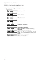
Release the four right-and-left snap
locks on the exhaust port lid and
remove the lid.
2.
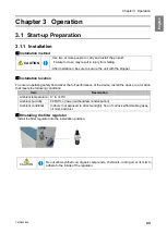
Take out the exhaust filter.
3.
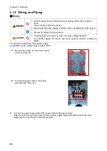
Attach a new exhaust filter.
4.
Reattach the exhaust port lid.
5.2
Daily Checkup
Check item
Frequency
Check that:
Each door
Before operation
Filter case is completely closed.
Suction port
Before operation
Suction port is not blocked.
Exhaust condition
Daily
Exhaust port is not blocked.
Operation panel
condition
Daily
Error or warning is not displayed.
Vibration of the unit
When in operation
Abnormal vibrations or noises
Status of the regulator
When in operation
Is air flowing?
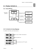
Exhaust port lid
Exhaust filter
Snap locks
Summary of Contents for CMP-2500AT3-A
Page 3: ......
Page 7: ...1 CMN209 006 3 1 1 1 1 2 10 60 80 1 3 0 40 80 100 1 000...
Page 8: ...1 4 1 4 2 OFF NV63 SVF 3P 30A 1 5...
Page 10: ...2 6 2 2 1 4 HEPA V1 1 1 1 1 AWG14 2 08...
Page 11: ...2 CMN209 006 7 2 2 2 2 1 CMP 2500 AT3 A V1 AT3 BOX HEPA V1...
Page 14: ...2 10 2 4 3 OP kPa SP kPa DP kPa EP kPa Blower Motor rpm Runtime h 17 Total h...
Page 15: ...3 CMN209 006 11 3 3 1 3 1 1 0 40 80 RH...
Page 16: ...3 12 3 1 2 200 230V 1 BOX 2 3...
Page 17: ...3 CMN209 006 13 1 2 8 3 2 1 RS485 ID 2 AT3 ON 3 4 1 7 3 ON OFF 3 30 ON OFF Ver ID...
Page 23: ...5 CMN209 006 19 5 OFF 2...
Page 24: ...5 20 5 1 WARN2 1 5 1 1 1 1 2 2 3 4 5 2...
Page 25: ...5 CMN209 006 21 5 1 2 1 1 1 2 2 2 3 4 1 5 6 2...
Page 26: ...5 22 5 1 3 V1 1 4 2 3 4 5 2 1 1 1 1...
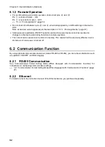
Page 29: ...5 CMN209 006 25 5 4 EL 1 2 3 4 1 4 30 1 1 5 1 20 5 1 20 5 1 20 5 1 20...
Page 31: ...6 CMN209 006 27 1 5V 0 2V B C ON HIGH LOW OFF LOW HI Z LOW DC 1 2...
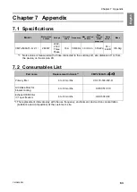
Page 35: ...7 CMN209 006 31 7 3 7 3 1 CMP 2500AT3 A...
Page 36: ...32 12 7 2 7 2 30...
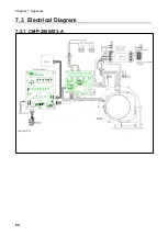
Page 68: ...Chapter 7 Appendix 64 7 3 Electrical Diagram 7 3 1 CMP 2500AT3 A Internal terminal...

