background image

チコーエアーテック株式会社 

Copyright CHIKO AIRTEC CO., LTD. 2009 


  5


1.4 

運転


Operation 


運転中に移動させないで下さい。


Do not move it during the operation. 


停電した時には、電源を切って下さい。復旧時に、けが・装置破損の原因になります。


Turn OFF the power when an instantaneous power interruption occurs. 
Otherwise, injury or product damage may be caused when the product recovers. 


フィルタを取り外したり、目詰まりや破損した状態で運転すると、


ブロア内への異物が混入して、故障の原因となります。  正しくフィルタを取り付けてご使用ください。


Operation  without  filter  or  with  a  clogged  and  damaged  filter  may  cause  trouble,  because  foreign 
substances enter the blower. Install the filter properly before operating the machine. 

1.5 

修理・分解・改造


Repair, disassembly and modification


本体を分解・改造しないで下さい。感電・けがの原因になります。内部の点検や修理はお買い上げになった販売店に
連絡して下さい。


Do not disassemble or modify the machine. 
Disassembly and modification may cause an electrical shock and injury. 
Contact your dealer for internal inspection and repair. 
 

1.6 

廃棄


Disposal


産業廃棄物として適切に処分してください。


Dispose of the product properly as industrial wast


2


製品到着時の確認

  Confirmation and Preparation at Arrival 


開梱されましたら、各部の不足部品がないかご確認下さい。


万一、運送途中での破損・部品不足などがございましたら、すぐにご連絡下さい。


After unpacking, make sure that all parts are provided. 

Contact our company immediately if parts are damaged during transportation or not provided. 


本体


Main Body


製品ネームプレートは本体に貼っていますので、ご確認下さい


Confirm the nameplate.


フィルタ(本体にセットされています)


Filter

set in the machine


1

次フィルタ

Primary filter

・・・・・・

080AT

FB-25

)×1               

500AT/1200AT(FB-30) 

×1


2

次フィルタ

Secondary filter

・・・・

080AT

CHF-2525-50

)×1   

500AT/1200AT(CHF-3030-50)

×1


排気フィルタ

Exhaust


filter

・・・・・

080AT

CHF-2525-50

)×1 

    500AT/1200AT(CHF-3030-50)

×


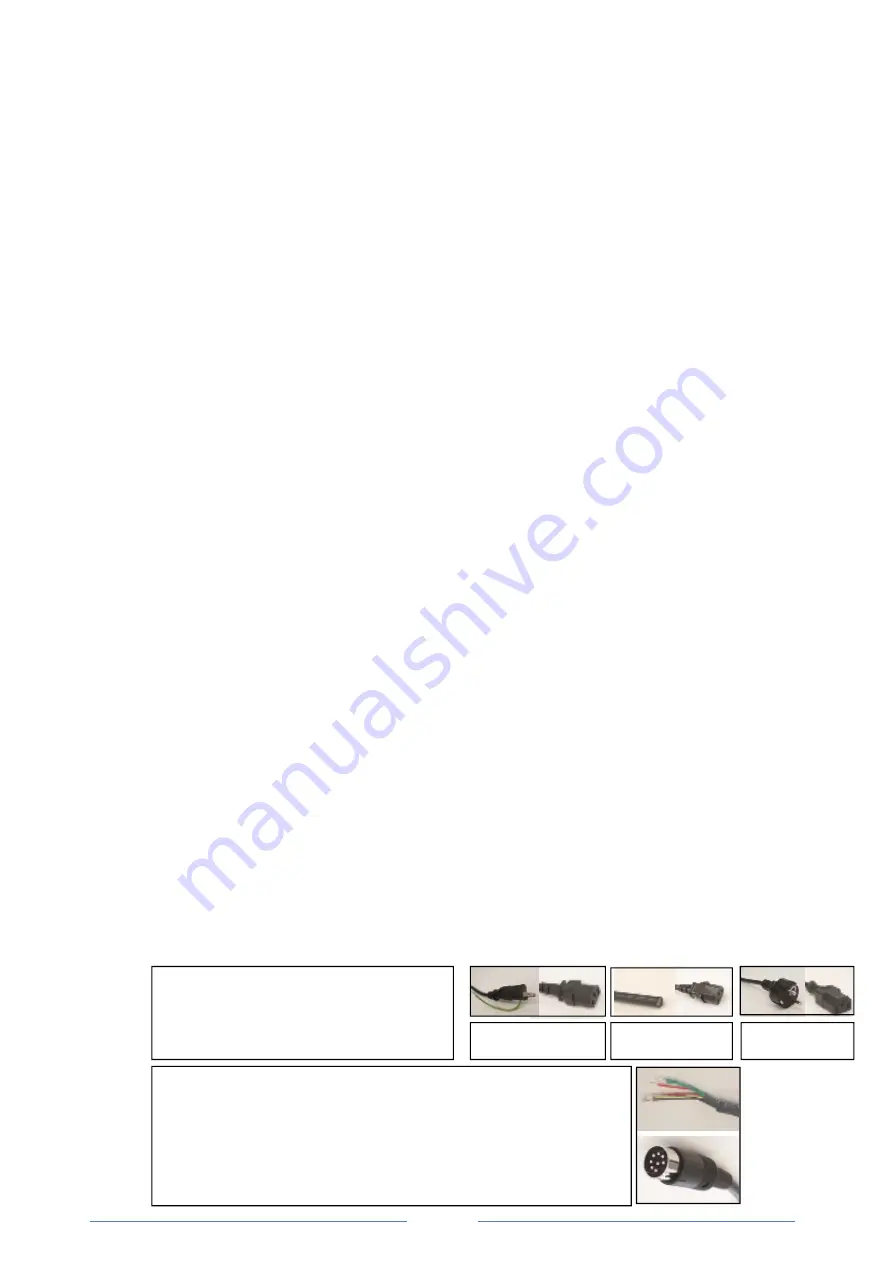
電源ケーブル(付属)とリモートケーブル(別売)


Power cable(standard accessory) and Remote cable(option) 


電源ケーブル

Power cable


(3m)  ×1 

※  ケーブルは地域によって異なります。 
※  The cable is different in each region.


リモートケーブル(別売)    MT-173-8 

Remote cable(option)

(3m)  ×1 

抜け防止の設計となっております。くぼみを下にし、しっかりと差し込んで
下さい。

(ピンの位置を必ず確認してください) 

The remote cable is so designed as to be prevented from falling off. 
Insert it securely with its dent facing downward. 
(Make sure to confirm pin positions.) 

100-110V 

200V 

国内

Japan


200V 

海外

Other than Japan


Summary of Contents for CBA-080AT-HC

Page 1: ...lead to a serious accident caused by incorrect handling CAUTION This symbol indicates cautions to assure safe use and actions that may lead to failure caused by incorrect handling Instruction Manual M...

Page 2: ...osene paint etc Explosive dust Aluminum magnesium titanium zinc epoxy etc Dust containing sparks Dust containing sparks generated by high speed cutters grinders welding machines etc Fire sources Cigar...

Page 3: ...onfirmation before operation 9 4 5 Operation procedure 10 5 Remote Cable Sold Separately 11 5 1 Electrical circuit diagram 11 5 2 Remote Cable 11 5 3 Color and signal of each wire 12 5 4 Remote operat...

Page 4: ...t outdoors 0 40 80 Install the product in a place without dew condensation at room temperature ambient temperature 0 to 40 C humidity 80 or less High temperature and dew condensation may cause electri...

Page 5: ...pair 1 6 Disposal Dispose of the product properly as industrial wast 2 Confirmation and Preparation at Arrival After unpacking make sure that all parts are provided Contact our company immediately if...

Page 6: ...rimary filter Collecting Adsorbing fine dust and fumes Secondary filter Protecting the circuit and the electrical parts Exhaust filter Exhaust treatment 3 Power cable 3m Exhaust port AT AT Panel opera...

Page 7: ...z CBA 1200AT HC V1 CE 200V 240V 50 60Hz CBA 2000AT HC V1 200V 50 60Hz 10 3m The allowable supply voltage range is 10 The power cable of 3 m with a grounding plug is included 4 2 AT AT panel Filter sat...

Page 8: ...o Push here to lower gradually suction speed Minimum Lo 40 power Hi 1 1 100 Hi Push here to increase gradually suction speed Maximum Hi 100 power ON OFF ON OFF switch and Main Power supply Light up Re...

Page 9: ...grounding plug are connected correctly insulation is provided properly and the rated voltage is realized Confirm the items 1 to 3 above and then proceed to the item 4 AT Turn ON the MAIN POWER switch...

Page 10: ...to a proper position Turn ON the MAIN POWER switch and confirm that the power indicator lamp lights Starts the dust collector AT ON Press the ON switch to start the operation 7 Choose operation abili...

Page 11: ...s put inside a shrinkable tube so that it cannot be short circuited with other wires Remote operation switch ON Shifting to remote mode Remote control is possible in the ON and the panel is impossible...

Page 12: ...panel is disabled while the wires 4 and 8 are short circuited Yellow white Black White Operation pressure signal Output signals Transfers the current operation output Analog signal 1 5V Impedance 4 7...

Page 13: ...in body Transfer required output signals in accordance with the explanation in 5 3 Color and signal of each wire AT ON Lo Hi Change with Lo Hi switch pushing the ON switch of main body AT panel when y...

Page 14: ...filter grid frame should be located on the exhaust side Make sure to turn OFF the main power and disconnect the power plug from the electrical outlet to cut off the electricity before starting inspec...

Page 15: ...s into the clearance on the left and right sides between the filter case and the filter to remove the filter easily Remove the primary filter from the filter case The paper packing of the primary filt...

Page 16: ...g operation Does the suction hose end offer proper suction force Is the clogging indicator lamp extinguished When the fuse is blown out by excessive current generated by a trouble in the internal equi...

Page 17: ...ing 1 to 3 above remove the cause of error and press the RESET switch Or turn OFF and ON the MAIN POWER switch to reset the error status Start the operation 30 minutes later Fuses are blown out 6 5 Re...

Page 18: ...IRTEC CO LTD 2009 18 8 Indication of DANGER Labels P r o h i b i t i o n l a b e l P r o h i b i t i o n o f d i s a s s e m b l y W a r n i n g l a b e l H i g h v o l t a g e P r o d u c t n a m e p...

Page 19: ...Copyright CHIKO AIRTEC CO LTD 2009 19 9 Electrical Circuit Diagram CBA 080AT HC 100V CBA 080AT HC CE 200 240V...

Page 20: ...Copyright CHIKO AIRTEC CO LTD 2009 20 CBA 1200AT HC CE CBA 500AT HC CE...

Page 21: ...s CBA 080AT HC V1 250 100 110 Single phase 4 5 50 60 1 5 8 5 54 67 10 0 CBA 080AT HC V1 CE 400 200 240 Single phase 3 0 50 60 1 5 7 8 8 9 200V 240V 54 67 14 5 CBA 500AT HC V1 450 100 110 Single phase...

Page 22: ...2525 50 V1 CBA 500AT HC V1 FB 30 CHF 3030 50 CHF 3030 50 HEP 3030 69 V1 CBA 500AT HC V1 CE FB 30 CHF 3030 50 CHF 3030 50 HEP 3030 69 V1 CBA 1200AT HC V1 FB 30 CHF 3030 50 CHF 3030 50 HEP 3030 69 V1 CH...

Page 23: ...emo about purchase Model Manufacturer s serial number Date of purchase Start of operation Your name Address Phone Person in charge LTD 562 0012 2 27 24 2 27 24 Hakushima Minoh City Osaka apan 562 0012...

Reviews: