Chapter 6
Useful
Utilization
(
Optional
)
CMN012-005
59
E
nglis
h
Chapter 6
Useful Utilization
(
Optional
)
6.1
Remote Cable
6.1.1
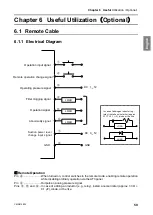
Electrical Diagram
■
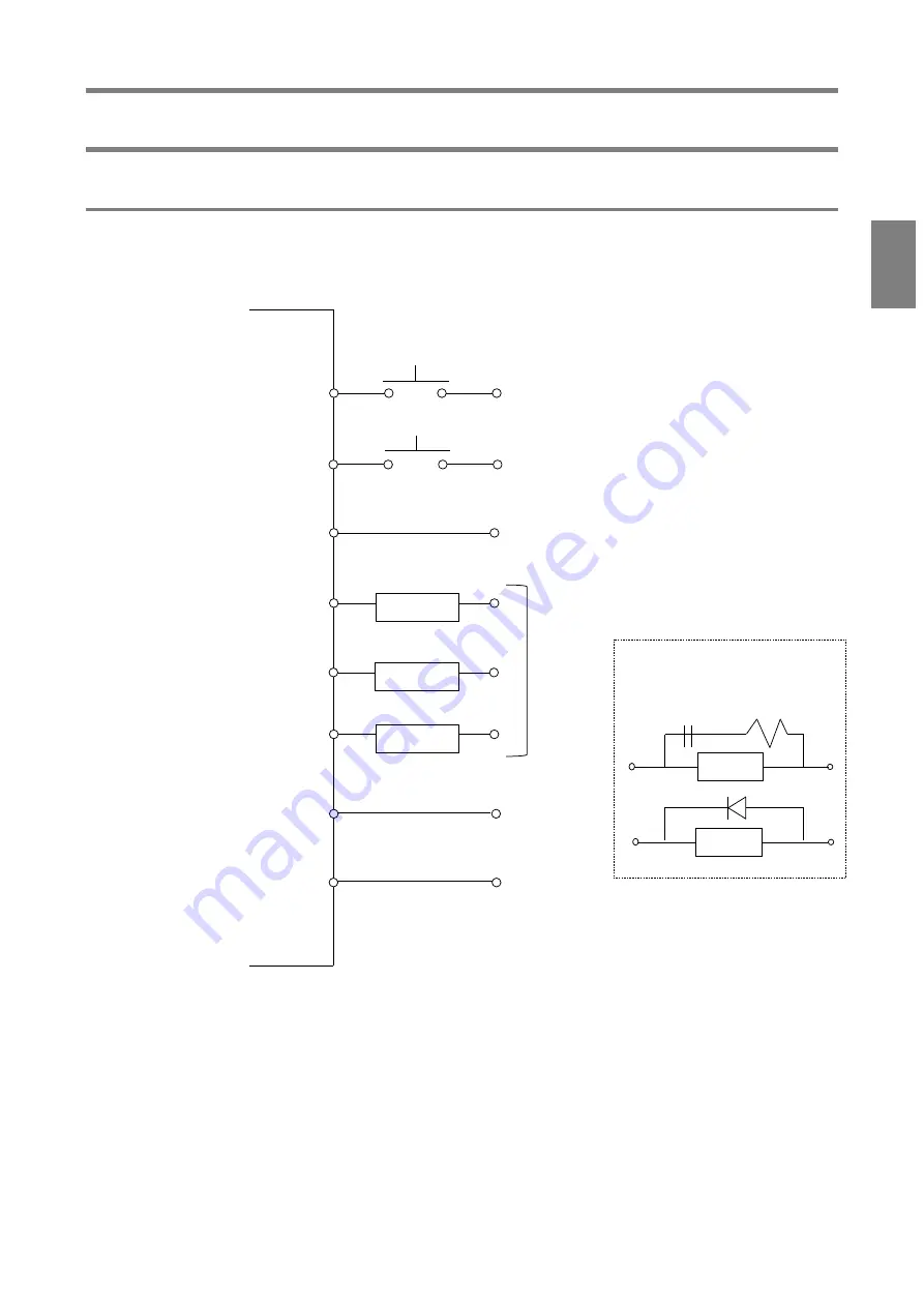
Remote Operation
Pin
④
.........................
When turned on, control switches to the remote mode, enabling remote operation
while disabling ordinary operation via the AT3 panel.
Pin
②
.........................
Outputs an analog pressure signal.
Pins
③
,
⑤
, and
⑥
...
In case of adding an inductor (e.g., relay), install a noise limiter (approx. 33 Ω +
0.1 μF), diode, or the like.
Operation input signal
Remote operation change signal
Operating pressure signal
Filter clogging signal
Operation signal
Abnormality signal
GND
④
⑤
⑦
③
②
⑧
⑥
DC
1
~
5V
In case of adding an inductor (e.g.,
relay), install a noise limiter (approx.
33
Ω
+ 0.1
μ
F), diode, or the like.
LOAD
LOAD
DC
0
~
5V
GND
①
LOAD
LOAD
LOAD
Suction power level
change input signal

