operation manual
EAR (WEEE): DE25841852
LUCID Packaging Act: DE5562476395648
GRS (UBA register) No .: 21003466
-
Product data sheet page 2/2 -
Status: 01/2020 - Ver. 1.01
Before starting the installation - power off at the main switch - check again that there is no voltage!
The installation or the intervention in the power grid can lead to very serious injuries up to a fatal electric
shock. • Connection or installation may only be carried out by qualified personnel / qualified electricians in
a voltage or current-free state! The absence of voltage must be checked! It is essential to observe the UVV
(accident prevention regulations) and VDE regulations! Operation only permitted on 230V ~ / 50Hz.
Installation may only be carried out with approved and tested tools. For all work, switch off the circuit in
which the installation is being carried out completely at the main fuse! Otherwise there is a DANGER TO
LIFE !!. To connect all 230V ~ / 50Hz components, the minimum cross-section (1.5mm²) of the connection
line must never be undershot. Be sure to use a cable that has been expressly approved for this use. There
are no serviceable parts inside this product. The correct connection must be checked; the voltage may
only be switched on again when the installation is correct. The circuit may only be put into operation
when all components have been properly and firmly installed in the wall / bracket / ceiling and checked
for full functionality. The permissible connection load must never be exceeded.
Before starting the installation - power off at the main switch - check again that there is no voltage!
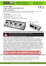
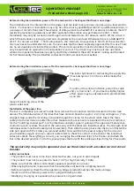
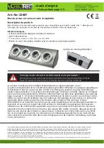
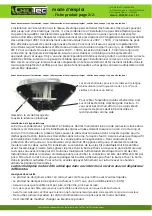
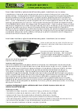
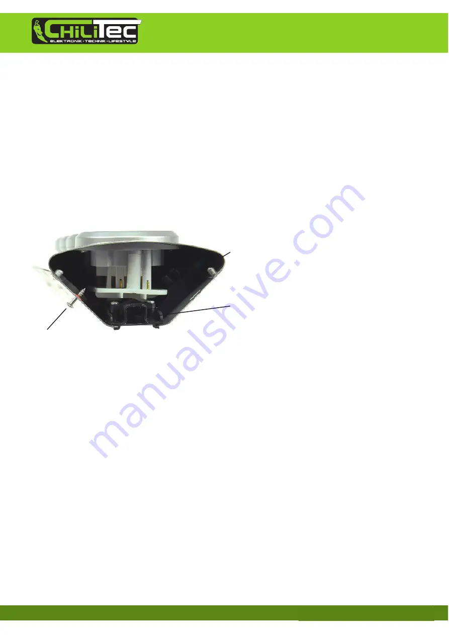
The luster terminals for connecting the supply line
(must always be 1.5mm²) are visible inside the
housing.
To pull out the entire end block, pull on the cable
entry / strain relief ... If you need a slightly higher
effort, pliers may be advisable and recommended
as an aid.
loosen the locking screw of the
plastic side cover
Installation of the power line
The bar is completely "pre-wired" inside. Now remove the connection terminal located in the bar (see
above). The individual wires of the lines that have arrived should be approx. 2 cm long and approx. 7 mm
stripped. Now guide the incoming, live cable through the clamp for the strain relief. Insert the three
cables into the terminal one after the other. Make sure that each wire is installed in the correct terminal
for the "matching counterpart". So PE protective conductor green / yellow on the opposite PE protective
conductor green / yellow. Proceed in the same way with the other two individual wires. The strength of all
individual wires must be checked prior to assembly. Then slide the clamp back into the bar and fasten the
side part again with the screw you removed earlier. Now switch on the power supply for the circuit of
your installation again and use a special cable tester to check the correct connection of the individual
wires per socket. If everything is correct, you can apply the adhesive strips to fix the bar and attach the
bar in the desired position. To do this, please press the bar with the adhesive strips firmly for 20 seconds.
The socket strip may only be operated in an earthed circuit with a residual current circuit
breaker.
safety instructions
•
The product must never come into contact with water, not even in other liquids.
•
The product must not be exposed to heat (> 40 °) or high humidity (> 80%).
•
Make sure that the cable is not kinked, squeezed, pinched or run over.
•
When laying the cable, make sure that the cable does not become a tripping hazard.
•
Before connecting, check that the operating voltage (product) matches the mains voltage.
•
Never touch the product, power cord or plug with damp hands.
•
Modifying, changing or expanding the product is not permitted.
Reproduction only with permission from ChiliTec GmbH, teaching


