Status: 12/2021 - Version 1.00
Page 2
Item No. 23214
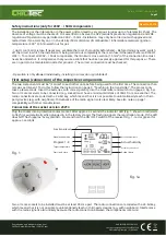
Safety instructions (only for 230V ~ / 50Hz components)
The installation or the intervention in the power grid can lead to very serious injuries up to a fatal electric shock. The
absence of voltage must be checked! • It is essential to observe the UVV (accident prevention regulations) and VDE
regulations! Operation only permitted on 230V ~ / 50Hz • Installation may only be carried out with approved and
tested tools • No assembly on or in the vicinity (50cm distance) of combustible / inflammable materials (ignition
temperature <200 ° C). Also watch out for gas
- / dust / room air mixture. If necessary, ventilate the room thoroughly beforehand. • Before doing any work, switch
off the circuit in which the installation is being carried out completely at the main fuse! Otherwise there is a RISK OF
LIFE !! • To connect all 230V ~ / 50Hz components, the minimum cross-section (1.5mm²) of the connection line must
never be undershot. It is imperative that you use a cable that has been expressly approved for this purpose. • There
are no parts to be maintained inside this product. • The correct connection must be checked;
• Operation is only allowed individually, installing in succession is prohibited!
First setup (connection) of the respective components
The two components must be “married” to each other once before being used for the first time. The connection then
remains permanent. To do this, follow the instructions on page 3. “Teaching in the transmitter”. The process only
takes a few seconds. Insert the batteries, with correct polarity, into the transmitter and switch it on (page 3, Fig. 3a).
Two or more receivers to be connected (e.g. socket) must have a minimum distance of 90cm from one another. The
radio connections are coded with a 24-bit key, which means that it is not possible to unintentionally teach in third-
party devices (e.g. with neighbors). Disturbance of the radio signal is also less likely. See also note on page 1,
compatibility with other manufacturers.
Connection of the socket version 23213
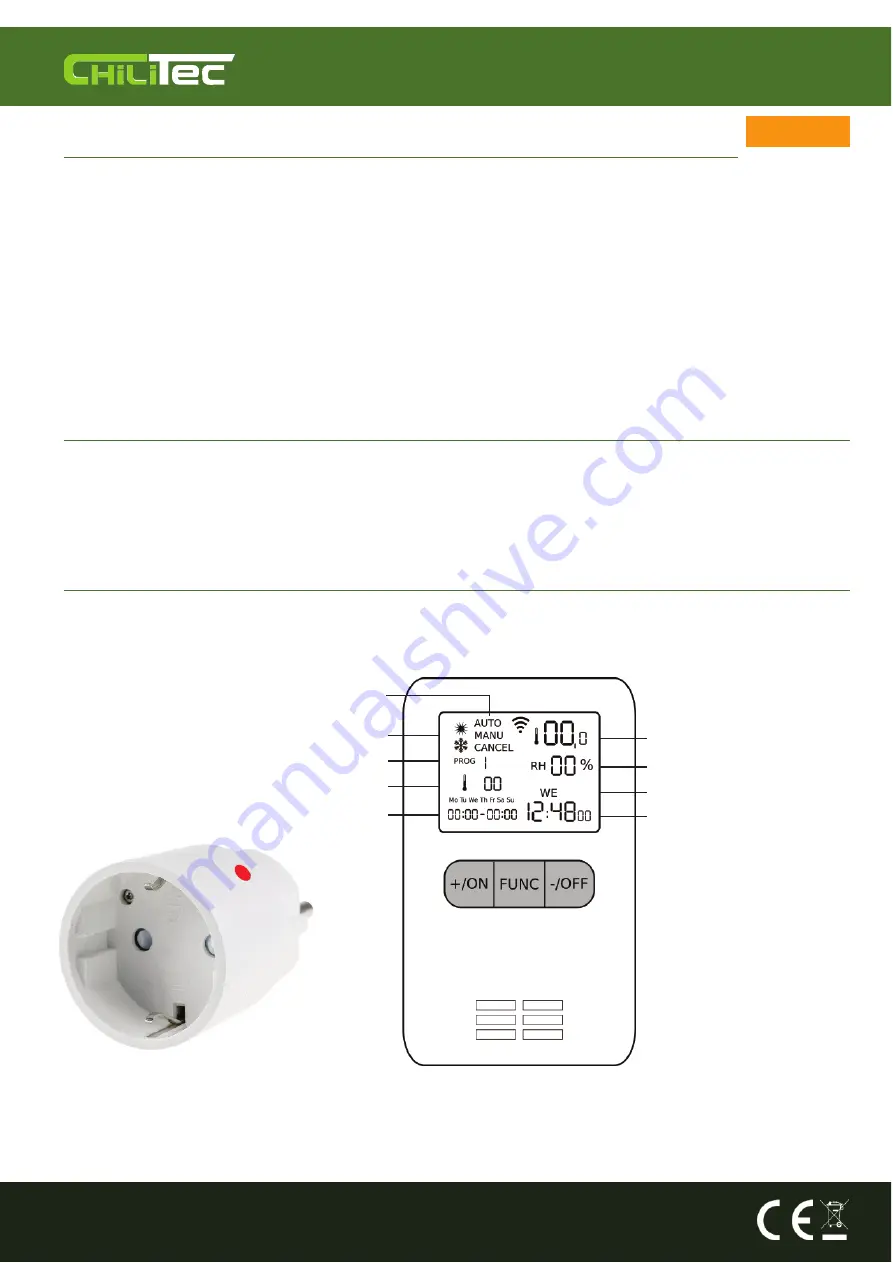
Plug the socket into a protective contact socket. After approx. 3 seconds the indicator LED (Fig. 1- shown in red) starts
to flash (or automatically when plugged in in the factory state!). The flashing signals the registration mode. If the LED
does NOT flash (approx. Every second) - Press and hold the ON / OFF switch of the receiver (Fig. 1 - red or green) for
approx. 3 seconds.
Functional level
Preselection mode
Actual temperature
Program 1-8
Target temperature
Actual humidity
Actual day of the week
Actual time
Fig. 1
Start / end time
Fig. 1a
Two or more sockets to be installed must be at least 90 cm apart. The radio connections are coded with a 24-bit key,
which means that it is not possible to unintentionally teach in third-party devices (e.g. with neighbors). Interference
with the radio signal is also unlikely because the radio connection between the components is secure.
Reproduction only with permission from
ChiliTec GmbH, Bäckerberg 12, 38165 Lehr
EAR (WEEE): DE25841852
LUCID Packaging Act: DE5562476395648
GRS (UBA register) no .: 21003466


