Chiltern Invadex LiteTrack Portable Gantry
8
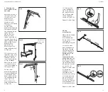
9. Securing the
cross beam to the
cassette
Adjust the position of
the leg as Fig 8.2 (B)
to allow the corner
quadrant to be
connected (this
should be at 90
degrees to the leg and
cross beam).
Pull the corner
quadrant back against
the leg and hold with
one hand against the
leg as Fig 9 (A).
Check the cross
beam has been
locked in position on
the legs. Be aware of
finger trapping hazard
when pulling corner
quadrant back
against the leg
.
Secure in position
using the handwheel
as Fig 9 (B).
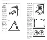
Fig 9
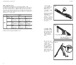
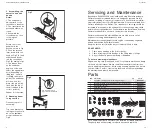
10. Place the second
leg within easy reach
and raise the end of
the beam. Place on
top of the second leg
as Fig 10.
Note:
Check the pin on the
cross beam sits on
top of the moulding on
the legs as Fig 10.
Fig 10
Pull the corner
quadrant back against
the leg (at 90 degrees
to the leg and cross
beam) and hold with
one hand against the
leg as Fig 11 (A).
Secure in position
using the handwheel
as Fig 9 (B).
Fig 11
A
B
A
Pin should sit
on top of the
moulding
User Guide
13
B
A
C
B
C
A
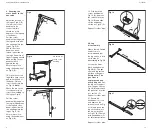
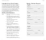
Fig 19
19. Fold back the
corner quadrant as
Fig 19 (A), depress
the release lever as
Fig 19 (B) and slide
out the end beam
section as Fig 19 (C).
Repeat for other side.
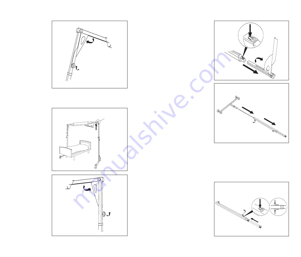
20. Leg
disassembly
Where there is limited
head room it is
recommended that
the leg section is laid
on its side for
disassembly as Fig 20.
Loosen the lower
black handwheel as
Fig 20 (A). The gas
strut and leg section
will then slide apart.
Safety note: The
gas strut is
compressed and
will spring out.
Pull
the leg section apart
from the gas strut as
Fig 20 (B) and remove
the gas strut from the
foot section (C).
Repeat for other side.
Fig 21
Fig 20
B
C
A
A
A
21. Ensure top
handwheel is loose
and depress the
release levers as Fig
21 (A) and push the
leg section down to
the lowest position
as Fig 21 (B). Fasten
both handwheels (C)
for safe transportation.
Repeat for other side.


