background image

Chiltern Invadex LiteTrack Portable Gantry

4

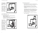
Check all components are available prior to assembly.

Notes:
If the gantry is to be assembled over a bed

The gantry can be assembled over a bed 

unless

 it is occupied. If the

bed is occupied assemble the gantry away from the bed and then
position afterwards (as a guide this would be approximately 900mm
from the head board but

always ensure the gantry track is directly

above the clients centre of gravity

).

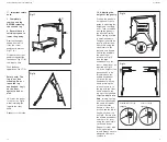
1. Preparation

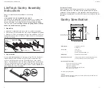
1. Unpack all components and lay on the floor ready for assembly.
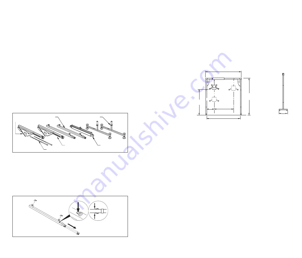
2. Check all parts are available (see Fig 1) and for damaged components.
3. Safety note: The corner quadrant located on the end beam (see Fig 1)
should always have tension. Check to ensure it does not swing freely
and there is tension.

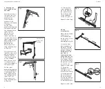
2. Leg assembly

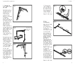
Loosen both black handwheels on the leg as Fig 2 (C & D). Push both
release levers in with one hand as Fig 2 (A), pull out the inner leg
section to the first position as Fig 2 (B) having let go of the release
levers.  This should then ‘click’ into place (the pin will be flush with the
top of the block when in the correct position). Secure the leg with the
locking knob Fig 2 (C). Note: The height of the unit can be adjusted later
when the gantry is fully assembled.

A

A

A

B

C

D

LiteTrack Gantry Assembly
Instructions

Fig 2

Foot section x 2

Leg section x 2

Cassette x 1

End beam x 2

Foot section x 2

Leg section x 2

Cassette x 1

Gas strut x 2

Corner 

quadrant x 2

Fig 1

User Guide

17

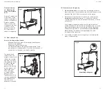
Lifting capacity

210 Kg (33 stone)(460 lb)
including hoist

Construction

Legs - steel
Track - Aluminium
Cassette - Aluminium with ABS cover

Lifting Range

Approximately 1525mm - 1825mm

Maximum loading per foot

100kg (16 stones) (220lb) (provided that the gantry is used in

accordance with the instructions in this user guide)

Assembled component weights:

Lower Leg section (x2) 7kg each (15.5lb)
Upper Leg section 8kg each (18lb)
Cassette (x1) 11kg (24lb)
End section/corner quadrant (x2) 5kg each (11lb)
Gas strut (x2) 1kg each (2.2lb)

Total weight of gantry 53kg (116lb)

CE MARK
The Chiltern Invadex Wispa LiteTrack Gantry carries the CE mark and complies with EC Directives:
Medical Device Directive(93/42/EEC)

Further assistance

Please telephone any Chiltern Invadex Office for further assistance.
Remember that service calls made after the guarantee period will be
chargeable.  If the maintenance of the equipment is the responsibility of a
third party, for example the Social Services, please contact them in the first
instance.

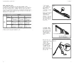
Gantry Specification

2165 - 2465
(50mm intervals)

1010 - 1530

440

Gantry at highest position 1825
Gantry at lowest position 1525

2040 - 2560

1890 - 2410 (Internal)

1100

Summary of Contents for OHWLTRK-1

Page 1: ...ax 028 9127 0046 Chiltern Invadex Ltd Unit 16 Evans Business Centre 68 74 Queen ElizabethAvenue Hillington Industrial Estate Glasgow G52 4NQ Tel 0141 880 9986 Fax 0141 880 9990 Copyright Chiltern Inva...

Page 2: ...this is contained on page 2 Intended use of the Product 2 Things to consider before using the Gantry 2 Assembly Guide 4 Disassembly guide 11 Servicing maintenance 15 Parts 15 Troubleshooting 16 Gantry...

Page 3: ...he gantry is assembled and adjusted for level using the spirit levels on the end beams There are only 3 width adjustment holes per end beam The pin must always be located in one of these Safety Safety...

Page 4: ...tle the gantry The hoist should be lowered onto a bed chair or a Chiltern Invadex transportation trolley before it is disconnected from the gantry track Always follow the assembly dissassembly instruc...

Page 5: ...gantry is fully assembled A A A B C D LiteTrack Gantry Assembly Instructions Fig 2 Foot section x 2 Leg section x 2 Cassette x 1 End beam x 2 Foot section x 2 Leg section x 2 Cassette x 1 Gas strut x...

Page 6: ...stuck on the leg end beam section Spring mechanism has failed on the leg end beam section and will not push in manually Height of feet cannot be adjusted Cannot check gantry is level Lifting eye on ca...

Page 7: ...ncy of servicing should be increased in areas where the environment or heavy usage may cause deterioration of the equipment Further details can be obtained from any Chiltern Invadex Office shown on th...

Page 8: ...reference guide to help determine the internal width of the gantry depending on the hole position which has been selected For example when the first hole position is selected on the end beam and the...

Page 9: ...d cross beam and hold with one hand against the leg as Fig 11 A Secure in position using the handwheel as Fig 9 B Fig 11 A B A Pin should sit on top of the moulding User Guide 13 B A C B C A Fig 19 19...

Page 10: ...ior to adjusting the height and checking level Take care when moving the gantry to the desired location Move one leg at a time in small increments The gantry should be level in all directions Check th...

Page 11: ...n the gantry Release sufficient tape to connect the carabena on the hoist to the eye on the gantry as Fig 14 Do not lift the hoist to attach it to the gantry Fig 14 Fig 15 Final positioning User Guide...

Page 12: ...n the gantry Release sufficient tape to connect the carabena on the hoist to the eye on the gantry as Fig 14 Do not lift the hoist to attach it to the gantry Fig 14 Fig 15 Final positioning User Guide...

Page 13: ...ior to adjusting the height and checking level Take care when moving the gantry to the desired location Move one leg at a time in small increments The gantry should be level in all directions Check th...

Page 14: ...d cross beam and hold with one hand against the leg as Fig 11 A Secure in position using the handwheel as Fig 9 B Fig 11 A B A Pin should sit on top of the moulding User Guide 13 B A C B C A Fig 19 19...

Page 15: ...reference guide to help determine the internal width of the gantry depending on the hole position which has been selected For example when the first hole position is selected on the end beam and the...

Page 16: ...ncy of servicing should be increased in areas where the environment or heavy usage may cause deterioration of the equipment Further details can be obtained from any Chiltern Invadex Office shown on th...

Page 17: ...stuck on the leg end beam section Spring mechanism has failed on the leg end beam section and will not push in manually Height of feet cannot be adjusted Cannot check gantry is level Lifting eye on ca...

Page 18: ...gantry is fully assembled A A A B C D LiteTrack Gantry Assembly Instructions Fig 2 Foot section x 2 Leg section x 2 Cassette x 1 End beam x 2 Foot section x 2 Leg section x 2 Cassette x 1 Gas strut x...

Page 19: ...tle the gantry The hoist should be lowered onto a bed chair or a Chiltern Invadex transportation trolley before it is disconnected from the gantry track Always follow the assembly dissassembly instruc...

Page 20: ...he gantry is assembled and adjusted for level using the spirit levels on the end beams There are only 3 width adjustment holes per end beam The pin must always be located in one of these Safety Safety...

Page 21: ...this is contained on page 2 Intended use of the Product 2 Things to consider before using the Gantry 2 Assembly Guide 4 Disassembly guide 11 Servicing maintenance 15 Parts 15 Troubleshooting 16 Gantry...

Page 22: ...Dealers Name Address Post Code Telephone Your Serial Number is Date of purchase Please fill in the information below for future reference Models covered OHWLTRK 1 OHWLTRK 2...

Page 23: ...ax 028 9127 0046 Chiltern Invadex Ltd Unit 16 Evans Business Centre 68 74 Queen ElizabethAvenue Hillington Industrial Estate Glasgow G52 4NQ Tel 0141 880 9986 Fax 0141 880 9990 Copyright Chiltern Inva...

Reviews: