background image


SNA8110T Gepon OLT User Manual


陈泽科技有限公司

                                                                                                                  www.stephen-tele.com 

will cause the Apply button to be enabled allowing the GUI operator to apply the new provisioning to the managed entity. 

3.1.2 Refresh Button


Button’s  labeled  refresh  are  never  disabled.  The  action  associated  with  a  Refresh  button  is  always  to  query  the  state  of  the 

associated attribute. The result of a successful Refresh operation will be the same as if the panel is viewed for the first time. That 

is,  the  OLT  will  query  the  managed  entity  associated  with  the  panel,  and  if  the  operation  completes  the  Apply  Button  will  be 

disabled. 

3.1.3 Revert Button


The  Revert  Button  had  identical  functionality  to  the  Refresh  button,  but  is  semantically  different.  The  idea  behind  the  Revert 

Button is that you can “revert” the panel’s state to the initial state of the panel prior to changing a GUI widget. Semantically, once 

the apply button has been pressed it is not possible to revert. The Revert Buttons are currently being phased out in favor of the 

Refresh Button. 

3.1.4 Defaults Button


The  Defaults  Button  is  used  to  restore  the  managed  entity  to  the  default  settings  found  in  the  Host  Interface  document.  This 

mechanism employs a “canned” Host Interface Message that will be issued to the OLT when the button action is invoked by left 

clicking on the button. 

For most commands a provisioning operation will also result in a subsequent query. In such cases the Apply Button will not be 

disabled until the query operation completes. This audit mechanism ensures that the values displayed by the panel are the same 

values stored in the relevant managed entity. For a few Host Interface Messages the granularity of the data is less than that of the 

provisioned value. 

Some Apply actions result in multiple commands being issued to the OLT. 

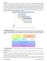
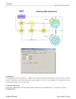
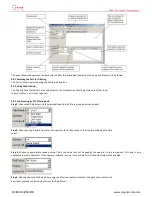
4 GUI Panel Directory


This section describes the various panels found in the GUI, their function, and the method by which they may be used to test the 

TK37XX Host Interface. The Panels are organized by entity and generally follow the order in which they appear in the associated 

tabbed dialog box. In the rare case that the GUI abstracts some detail of the host interface, a flow chart of the message exchange 

sequence  is  presented.  Where  the  message  performs  a  complex  operation  on  the  PON  a  related  diagram  may  be  present  as  a 

visual aid. Most panels are subdivided into boxes with each box controlling exactly one host interface message. In most cases the 

attributes  are  presented  in  the  same  order  (as  read  from  top  to  bottom)  as  that  in  which  they  appear  in  the  Host  Interface 

Message. Thus for the most part the remainder of this document is simply a rehashing of the descriptions already available in the 

Host Interface Document. 

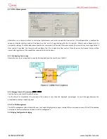
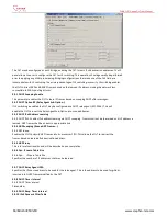
Force  link  rediscovery  de-registers  a  Logical  Link,  while  allowing  it  to  re-register,  as  if  it  had  been  newly  attached  to  the  EPON 

network. This command is useful, for example, when the Network operator wants to be able to force a re-arrival as part of their 

debugging process to try to clear a problem, or to re-authenticate the user/ONU on that link. 


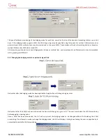
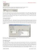
The Block Link command prevents the given Logical Link (MAC address) from registering on the EPON. The OLT will simply ignore 

registration requests from the blocked ONU. If the given ONU is already registered, the Logical Link will be deregistered, causing 

the ONU to depart from the network. All further requests to register from the ONU are ignored until the Host issues an Unblock 

Link command. 

Up to 256 ONU labels (MAC addresses) can be on the block list at one time. 

Link blocking is intended to be a temporary measure used to suspend service for reasons such as late payments or a troublesome 

customer. When the issue has been resolved, or the ONU has been physically removed from the network and no longer requests 

service, it can be removed from the blocked list with the Unblock Link command. If the ONU is still connected to the network and 

attempting to register, the ONU will be once again allowed onto the network. 

Service provisioning such as SLAs or Bridging modes are not affected by the Block Link command. Any ONU provisioning should be 

deleted with the appropriate other commands, if desired. A blocked link will appear with a black status icon. 

Please note the difference in the behavior with respect to the Block Link command where an Unblock Link is required to undo its 

effect.  Link  Rediscovery  invites  the  ONU  to  re-register  this  link  with  the  network,  while  Block  Link  prevents  the  ONU  from 

returning on that link after deregistration. 


Summary of Contents for SNA8110T

Page 1: ...SNA8110T Gepon OLT User Manual www stephen tele com SNA8110T GEPON SYSTEM OLT User Manual STEPHEN TECHNOLOGIES CO LIMITED ALL RIGHTS RESERVED...

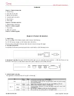
Page 2: ...and a switch button as the following picture 3 Back panel instruction Back panel of ONU from left to right in turn is 16 kinds of status indicators a PON Port fiber port two RJ45 Ports a bunch port a...

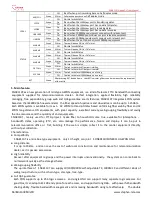
Page 3: ...exibility high reliability managing free expansibility group web and QoS guarantee are its features SNA8110T integrates EPON system based on the IEEE802 3ah new standard the fiber speed of upstream an...

Page 4: ...ter 2 Installation and link 1 Attention item for setting Please insure that there is suitable work environment and enough free space before installing machine Please note the installing requirement as...

Page 5: ...r consists of the underlying messaging system used by the GUI This layer is responsible for parsing and queuing of Host Interface Messages as well as providing reliability The next layer is the applic...

Page 6: ...to the OLT Thus that depending on very minor timing differences between command response times the GUI event log trace will be different It is important to note that all host interface messages are r...

Page 7: ...low chart of the message exchange sequence is presented Where the message performs a complex operation on the PON a related diagram may be present as a visual aid Most panels are subdivided into boxes...

Page 8: ...alue ms When the timer expires the loopback will automatically be canceled 6 3 MPCP Parameters 6 3 1 Period The interval at which the OLT will issue a discovery gate 6 3 2 Window The discovery window...

Page 9: ...NU deployment 7 2 Aggregate Shaper This command lets the Host restrict the bandwidth available to the OLT for user data traffic in each direction This feature can be used to protect the core network f...

Page 10: ...plying this command otherwise the OLT FIFOs will become corrupt It is recommend that this operation be performed once during the initial bring up of the PON 7 4 Shaper Drop Down Weights This command i...

Page 11: ...mine if it has any data to transmit Smaller values result in lower latency and increased overhead For priority 0 the scheduling latency is approximately equal to the larger of the polling rate and the...

Page 12: ...the host to disable SLA s It is important to note that though the logical link panel appears grouped under the ONU logical link attributes are NOT necessarily attributes of the ONU itself Logical link...

Page 13: ...e flow control Note however that pause frames will be transmitted regardless of the capabilities reported by the link partner 8 1 1 Configuring Port in Loop Allows the user to set a loop back currentl...

Page 14: ...mode However multiple links each provisioned in a different mode may be associated with a given egress ONU port 9 1 1 Changing the bridging mode for a particular logical link Notice that after the bri...

Page 15: ...rovisioning box a second box appears to the right that is used to display a list of all logical links in the provisioned VLAN No links will be displayed in this box until the VLAN provisioning is appl...

Page 16: ...user to select the VID The VID will be inserted into upstream frames arriving on links provisioned in the VLAN Downstream the VID will be used for classification 9 1 6 2 Upstream CoS The upstream CoS...

Page 17: ...tructing an OLT Filtering Rule Step 1 Choose the Field Select Field Selects defined by the OLT are given a descriptive label Step 2 Choose an appropriate Operator The operator tests the portion of the...

Page 18: ...nce levels 0 being the highest priority and 7 being the lowest Currently the precedence level of user provisioned filtering rules is of little importance Step 3 Add the filtering rule to the OLT by cl...

Page 19: ...relay agent RFC 3046 This will enable the OLT to insert the Relay Agent Sub Option into snooped frames 9 3 3 DHCP IPv4 Address Learning 9 3 3 DHCP IPv4 Enables IPv4 address learning via DHCP snooping...

Page 20: ...nclude A common management interface for ONU and OLT alarms Soak of alarms on a per alarm ID basis Auditing of all alarms known to the OLT Setting of alarm thresholds for ONU and OLT alarms Autonomous...

Page 21: ...was cleared in the column labeled Disposition The GUI has 3 different alarm dispositions autonomous audit and internal 10 2 Enabling alarm auditing The GUI can be configured to perform a periodic aud...

Page 22: ...alling thresholds and then click the apply button When the transaction completes successfully the Apply and Revert buttons will turn grey indicating that the OLT and GUI values are synchronized Note t...

Page 23: ...ion of user data traffic and filtering of user data traffic Because these operations are very complex the user interface is divided between several panels The ONU Queue configuration panel allows the...

Page 24: ...he full FIFO name is 1 2 indicating that the FIFO is 2 of User Port 1 11 1 2 Provisioning Number of Logical Links to Register Up to 3 Links may be registered per ONU 6 on a TK3711 The number of Logica...

Page 25: ...urpose of the Flooding FIFO is beyond the scope of this document 11 1 5 Provisioning Upstream FIFOs Step 1 Adding a FIFO to an ONU Logical Link is a similar procedure First click on either of the ONU...

Page 26: ...from the Quick Cfg drop down box or typing its name and clicking the Delete button Notice that the GUI prevents the user from adding more FIFOs than the ONU supports It will also prevent the user from...

Page 27: ...Engine Most ONU classification engines are configured on a per port basis However the TK3701 supports only upstream and downstream classification The Port field allows the operator to choose the set o...

Page 28: ...ssing the mouse button at the start of the field dragging it to the end of the field and then releasing the mouse button Notice that after the field has been selected the Name will change to reflect t...

Page 29: ...t Field Selects defined by the ONU are given a descriptive label User Defined field selects are labeled User 1 User 2 User N All field select labels begin with an index value The index value correlate...

Page 30: ...is classified A classification rule with higher precedence than a filtering rule can be used to override a filtering function Step 2 Select the FIFO for classification First select the ingress port th...

Page 31: ...ng Q The GUI Uses the convention Entity ID FIFO Number to denote a particular FIFO The Entity ID corresponds to link index upstream and the ONU User Port upstream If you forgot to add the Link Index c...

Page 32: ...In the previous section we learned that Classification Rules are used to allow certain classes of traffic into the ONU data path As you might imagine Filtering Rules serve the opposite purpose blocki...

Page 33: ...ering Rule Step 1 Select the Port to Filter Step 2 Set the rule precedence level The Rule Level may be configured for 1 of 8 different precedence levels 0 being the highest priority and 7 being the lo...

Page 34: ...s as an RFC 2236 non querier aggregating the reports sent by the several connected hosts and making the system appear to an attached video server or other device connected to the OLT s NNI as if there...

Page 35: ...ovisioned to a very large value Query Response Timeout units after the OLT issues the General Query the OLT will decrement the robustness variable for each group joined for which the OLT has not recei...

Page 36: ...e enabled only if the authentication succeeds Otherwise if checked SLAs will be enabled unconditionally This is useful for strict boot mode Enable OLT after boot If checked this attribute will cause t...

Page 37: ...ww stephen tele com Select the objective upgrade file as following Click open button then the ONUsoftware upgrade will finish 4 2 OLT software upgrade The process of OLT software upgrade is the same w...

Page 38: ...is document The information provided by this document is believed to be accurate and reliable to the publication date of this document However Stephen Technologies Co LTD assumes no responsibility for...

Reviews: