EM11 User’s Manual
3. Installation of Frequency Inverter
27
It is forbidden to short circuit the shielding layer and other signal cables and the equipment.
When the inverter is connected to the inductive load equipment (e.g. electromagnetic contactor, relay
and solenoid valve), surge suppressor must be installed on the load equipment coil, as showed in
Diagram 3-10
Diagram 3-10 Application example of inductive load surge suppressor
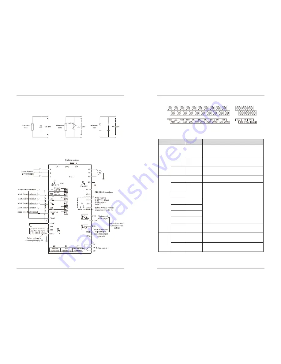
3.10 Control Circuit and Main Circuit Terminals Description
3.10.1 Control Circuit and Main Circuit Wiring
Diagram 3-11 Control Circuit and Main Circuit Wiring
3. Installation of Frequency Inverter
EM11 User’s Manual
28
3.10.2 Control Circuit Terminal Layout
Diagram 3-12 EM11 Control Circuit Terminal Sketch Map
3.10.3 Description of control circuit terminals
Table 3-4 Description of control circuit terminals
Type
Terminal
Symbol
Terminal
Name
Terminal function description
Power
Supply
+10V-GND
External
+10V power
supply
P10V power supply to external unit. Maximum
output current:10mA
Generally, it provides power supply to external
potentiometer with resistance range of 1 k
Ω
~5k
Ω
+24V-COM
External
+24V power
supply
P24 V power supply to external unit. Generally, it
provides power supply to DI/DO terminals and external
sensors. Maximum output current: 200 mA
J4
External
power supply
input terminal
Connect to +24 V by default.
When DI1-DI6 need to be driven by external signal, J4
must switch to be “OFF” status.
Analog
input
AI1-GND
Analog input
terminal 1
1. Input voltage range: DC 0V~10 V
2. Input Impedance: 22 k
Ω
AI2-GND
Analog input
terminal 2
1. Input range: DC 0V~10V/ 0mA~20mA, decided by
jumper J5 on the control board
2. Impedance: 22 k
Ω
(voltage input), 500
Ω
(current input)
Digital
input
DI1
Digital input
1
1. Optical coupling isolation, compatible with dual polarity
input
2.Input Impedance: 2.4 k
Ω
3. Voltage range for level input: 9V~30 V
DI2
Digital input
2
DI3
Digital input
3
DI4
Digital input
4
DI5
Digital input
5
HDI
High Speed
Pulse Input
Terminal
Besides features of DI1~DI5 and it can be used for
high-speed pulse input.
Maximum input frequency: 50 kHz
Analog
output
AO1-GND
Analog
output
terminal 1
Voltage or current output is decided by jumper J6.
Output voltage range: 0V~10 V
Output current range: 0mA~20 mA
AO2-GND
Analog
output
terminal 2
Output voltage range: 0V~10V


