EM11 User’s Manual
5. Description of Function Codes
65
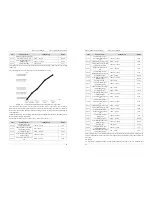
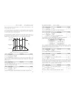
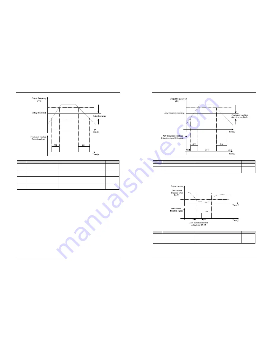
Diagram 5-15 Detection range of frequency reached
Code
Parameter Name
Setting Range
Default
b4-27
Any frequency reaching
detection value 1
0.00 Hz ~ maximum frequency
50.00 Hz
b4-28
Any frequency reaching
detection amplitude 1
0.0%~100.0% (maximum frequency)
3.0%
b4-29
Any frequency reaching
detection value 2
0.00 Hz ~ maximum frequency
50.00 Hz
b4-30
Any frequency reaching
detection amplitude 2
0.0%~100.0% (maximum frequency)
3.0%
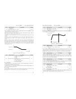
If the output frequency of the frequency inverter is within the positive and negative amplitudes of the any
frequency reaching detection value, the corresponding DO becomes ON.
The EM11 provides two groups of any frequency reaching detection parameters, including frequency
detection value and detection amplitude, as shown in the following figure.
5. Description of Function Codes
EM11 User’s Manual
66
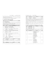
Diagram 5-16 Any frequency reaching detection
Code
Parameter Name
Setting Range
Default
b4-31
Zero current detection level
0.0%~100.0% (rated motor current)
5.0%
b4-32
Zero current detection delay
time
0.00s~600.00s 0.10s
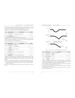
If the output current of the frequency inverter is equal to or less than the zero current detection level and the
duration exceeds the zero current detection delay time, the corresponding DO becomes ON. The zero current
detection is shown in the following figure.
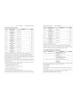
Diagram 5-17 Zero current detection
Code
Parameter Name
Setting Range
Default
b4-33
Over current output threshold
0.0%~300.0% (rated motor current)
200.0%
b4-34
Over current output detection
delay time
0.00s~600.00s 0.10s
If the output current of the frequency inverter is equal to or higher than the over current threshold and the
duration exceeds the detection delay time, the corresponding DO becomes ON. The output over current
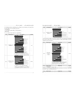
detection function is shown in the following figure.


