EM11 User’s Manual
5. Description of Function Codes
73
Different from DI terminals, VDI state can be set in two modes, selected in b7-05:
For example 1:Decided by state of VDOx
Whether the state of VDI is valid or not, that is determined by the state of the corresponding VDO. VDI x is
uniquely bound to VDO x (x is one of 1~5). For example, to implement the function that the frequency
inverter reports an alarm and stops when the AI1 input exceeds the limit, perform the following setting:
1.
Set VDI1 with function 44 "User-defined fault 1" (b7-00 = 44).
2.
VDI1 terminal valid is decided by state of VDO1 (b7-05= xxx0).
3.
Set VDO1 with function "AI1 input limit exceeded" (b7-11 = 31).
When the AI1 input exceeds the limit, VDO1 becomes ON. At this moment, VDI1 becomes ON and the
frequency inverter receives you-defined fault 1. Then the frequency inverter reports Err27 and stops.
Example 2: Decided by b7-06
The VDI state is determined by b7-06. For example, to implement the function that the frequency inverter
automatically enters the running state after power-on, perform the following setting:
1.
Set VDI1 with function 1 "Forward RUN (FWD)" (b7-00 = 1).
2.
Set b7-05 to xxx1: The state of VDI1 is decided by b7-06.
3.
Set b7-06 to xxx1: VDI1 is valid.
4.
Set b0-02 to 1: The command source to terminal control.
5.
Set b2-32 to 0: Startup protection is not enabled.
When the frequency inverter completes initialization after power-on, it detects that VDI1 is valid and VDI1
is set with the function of forward RUN. That is, the frequency inverter receives the forward RUN command
from the terminal. Therefore, the frequency inverter starts to run in forward direction.
Code
Parameter Name
Setting Range
Default
b7-07
Function selection for AI1
used as DI
0~49
0
b7-08
Function selection for AI2
used as DI
0~49
0
b7-09
Function selection for AI3
used as DI
0~49
0
b7-10
Valid state selection for AI
used as DI
Unit's digit: AI1.
0: High level valid
1: Low level valid
Ten's digit: AI2.
0, 1 (same as unit's digit)
Hundred's digit: AI3.
0, 1 (same as unit's digit)
0
The functions of these parameters are to use AI as DI. When AI is used as DI, the AI state is high level if the
AI input voltage is 7 V or higher and is low level if the AI input voltage is 3 V or lower.
If the AI input voltage is between 3 V and 7 V, the AI state is hysteresis. And then b7-10 is used to
determine whether high level valid or low level valid when AI is used as DI.
The setting of AI (used as DI) function is the same as that of DI. For details, see the descriptions of DI
setting.
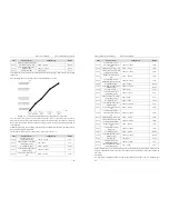
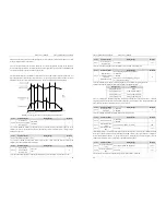
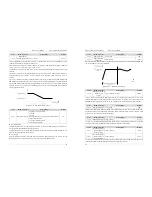
The following figure takes AI input voltage as an example to describe the relationship between AI input
voltage and corresponding DI state.
5. Description of Function Codes
EM11 User’s Manual
74
Diagram 6-22 Relationship of AI input voltage and corresponding DI status
Code
Parameter Name
Setting Range
Default
b7-11
VDO1 function selection
0: connect with physical DIx internally
1~38
38
b7-12
VDO2 function selection
0: connect with physical DIx internally
1~38
38
b7-13
VDO3 function selection
0: connect with physical Dix internally
1~38
38
b7-14
VDO4 function selection
0:connect with physical Dix internally
1~38
38
b7-15
VDO5 function selection
0: connect with physical Dix internally
1~38
38
b7-16 VDO1
output
delay 0.0s~3000.0s
0.0s
b7-17 VDO2
output
delay 0.0s~3000.0s
0.0s
b7-18 VDO3
output
delay 0.0s~3000.0s
0.0s
b7-19 VDO4
output
delay 0.0s~3000.0s
0.0s
b7-20 VDO5
output
delay 0.0s~3000.0s
0.0s
b7-21
VDO valid state selection
Unit's digit: VDO1.
0: Positive logic valid
1: Reverse logic valid
Ten's digit: VDO2
0, 1 (same as unit's digit)
Hundred's digit: VDO3.
0, 1 (same as unit's digit)
Thousand's digit: VDO4.
0, 1 (same as unit's digit)
Ten thousand's digit: VDO5.
0, 1 (same as unit's digit)
00000
VDO functions are similar to the DO functions on the control board. The VDO can be used together with
VDI x to implement some simple logic control.
If VDO function is set to 0, the state of VDO1 to VDO5 is determined by the state of DI1 to DI5 on the
control board. In this case, VDOx and DIx are one-to-one mapping relationship.
If VDO function is set to non-0, the function setting and use of VDOx are the same as DO in group b4.
The VDOx state valid can be set in b7-21. The application examples of VDIx involved the usage of VDOx,
and please see these examples for your reference.


