EM11 User’s Manual
5. Description of Function Codes
121
It displays the phase Z counting of the present ABZ or UVW encoder. The value increases or decreases by
1 every time the encoder rotates a round forwardly or reversely. You can check whether the installation of
the encoder is normal by viewing U0-45.
Code
Parameter Name
Display Range
U0-46
Present setting
frequency (%)
-100.00%~100.00%
U0-47
Present running
frequency (%)
-100.00%~100.00%
It displays the present setting frequency and running frequency. 100.00% corresponds to the frequency
inverter's maximum frequency (b0-13).
Code
Parameter Name
Display Range
U0-48
Frequency inverter
running state
0~65535
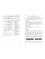
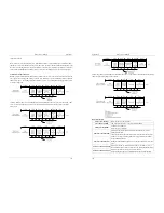
It displays the running state of the frequency inverter. The data format is listed in the following table:
U0-48
Bit0
Bit1
0: stop
1: forwarder running
2: reverse running
Bit 2
Bit3
0: constant speed
1:acceleration
2:deceleration
Bit 4
0:Normal DC bus voltage
1:Low DC bus voltage
Code
Parameter Name
Display Range
U0-49
Sent value of
point-point
communication
-100.00%~100.00%
U0-50
Received value of
point-point
communication
-100.00%~100.00%
It displays the data at point-point communication. U0-49 is the data sent by the master, and U0-50 is the
data received by the slave.
5.24 Group A0: System parameters
Code
Parameter Name
Setting Range
Default
A0-00
User password
0~65535
0
If it is set to any non-zero number, the password protection function is enabled. After a password has been
set and taken effect, you must enter the correct password in order to enter the menu. If the entered password
is incorrect you cannot view or modify parameters.
If A0-00 is set to 00000, the previously set user password is cleared, and the password protection function
is disabled.
5. Description of Function Codes
EM11 User’s Manual
122
Code
Parameter Name
Setting Range
Default
A0-01
Product number
Frequency inverter product number
Model
dependent
A0-02
Software version
Software version of control board
Model
dependent
A0-07
Parameter
modification property
0: Modifiable
1: Not modifiable
0
It is used to set whether the parameters are modifiable to avoid mal-function. If it is set to 0, all parameters
are modifiable. If it is set to 1, all parameters can only be viewed.
Code
Parameter Name
Setting Range
Default
A0-08
Individualized
parameter display
property
Unit's digit: User-defined parameter QUICK display
selection.
0: Not display
1: Display
Ten's digit: User-changed parameter QUICK display
selection.
0: Not display
1: Display
0
The setting of parameter display mode aims to facilitate you to view different types of parameters based on
actual requirements.
If one digit of A0-08 is set to 1, you can switch over to different parameter display modes by pressing key
“QUICK”. By default, only the “frequency inverter parameter” display mode is used.
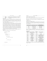
The display codes of different parameter types are shown in the following table.
Table 6-10 Display codes of different parameter types
Parameter Type
Display Code
Frequency inverter parameter display
-dFLt
User-defined parameter display
-user
User-changed parameter display
-cHGd
The EM11 provides display of two types of individualized parameters: user-defined parameters and
user-modified parameters.
You-defined parameters are included in group “A1”. You can add a maximum of 32 parameters, convenient
for commissioning.
In user-defined parameter mode, symbol "u" is added before the function code. For example, b0-00 is
displayed as ub0-00.
In “User-changed parameter” mode, symbol "c" is added before the function code. For example, b0-00 is
displayed as cb0-00.
The User-changed parameters are grouped together in QUICK menu, which is convenient for on-site
troubleshooting.
Code
Parameter Name
Setting Range
Default
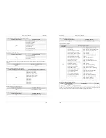
A0-09
Restore default
settings
0: No operation
1: Restore default settings except motor parameters
and accumulation record.
2: Restore default settings for all parameters
3: Reserve
4: Clear records
Ohter: Reserve
0

