8
Exercises recommended by Chinesport
One of the most recurring factors in the onset of any back conditions is no doubt to do with a micro trauma
resulting from an incorrect load distribution on the lumbosacral junction.
To understand how this condition arises, we need to understand the biomechanics of how forces spread
through the spine; we draw from Tony Nett's "Muscletraining" studies (1967) as it provides a comprehensive
explanation on this topic.
Fig. 1 A
Fig. 1B
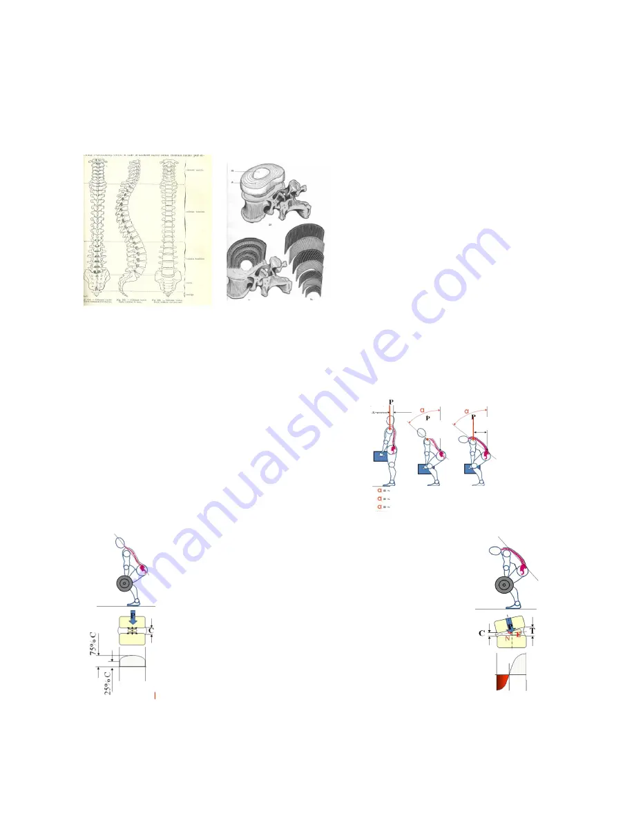
We know the spine has 33 bony segments
(vertebrae) that are stacked and interlinked
between them (Fig. 1A). The spine is highly
flexible thanks to the intervertebral discs that
separate the vertebrae and act as shock
absorbers, so any pressures causing a strain on
the spine are cushioned.
The intervertebral disc structure consists of two
different parts: a central part and a peripheral
part. The central part is called nucleus (N - Fig.
1B), while the peripheral part is called fibrous ring
(A - Fig. 1B) and is formed by a series of
concentric fibrous layers that cross obliquely.
This system keeps the pressure in the nucleus equalized in a stiff shell that stops any possible leak (Fig. 1B).
This clever structure is particularly resistant to compression, but it has one single "defect": the lack of blood
vessels means that, should the disc tissue be damaged or destroyed, it cannot be repaired or replaced.
After this brief introduction, we can use some mechanical calculations to analyze the loads affecting the disc
between the fifth lumbar vertebra and the first sacral vertebra (L5-S1), a disc that seems to suffer the most
stress as, when we stand, it is subjected to a permanent load that is the equivalent of the weight of the trunk
plus the weight of the upper limbs and the head.
If we take a person who is 180 cm tall and weighs 93 kg, who is
lifting a 30 kg load (Fig. 2), if we consider that disc L5-S1
supports the weight of trunk, upper limbs and head in addition to
the load, we can show some examples of the situations created
as a result of the upper body bending (increase in the length of
the lever) and reaching the following values:
Fig. 2
Fig. 3Aa, 3Ab, 3Ac
We need to point out that, on bending, loads are spread axially (Fig.
3A), so when a force "P" is applied through the vertebral plate the
disc is compressed and widens, the nucleus flattens, its internal
pressure increases significantly and spreads laterally towards the
outer ring fibers, causing tension to increase (Fig. 3Aa); this means
that a vertical load turns into lateral compression as a result of the
nucleus spreading the pressure (Fig. 3Ab).
Instead, when the upper body flexes, the upper vertebra slides
forwards and tilts towards the side with the heavier load, which
reduces the intervertebral space at the front (Fig. 3B).
With static work on a slightly bent vertebra, force "P" splits into a
force "N" that firmly presses the upper vertebra down onto the lower
vertebra, and a force "E" that tends to push the nucleus back against
the fibrous ring, increasing tension at its back and creating a situation
of tension on the back fibers of the intervertebral disc.
Fig. 3Ba, 3Bb, 3Bc
As discs are highly resistant to compression but do not stretch easily, such a situation combined with an
excessive load causes a traumatic effect which, if repeated several times, can lead to small cracks and cavities
in the fibrous ring that may allow the nucleus matter to filter through.
Lever
Lever
angle
Lever angle
10° on disc L5-S1 means a 207 kg load
50° on disc L5-S1 means a 593 kg load
90° on disc L5-S1 means a 728 kg load
Co
m
p
re
ss
io
n
T
ra
c
ti
o
n
angle


