INST No. INE-403-0P0
−
14
−
5.1
Names and functions
of detector unit
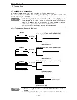
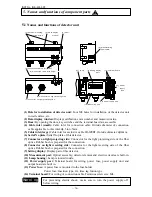
(1) Hole for installation of detector unit:
Four M8 holes for installation of the detector unit
to wall surface, etc.
(2) Data display window:
Displays calibration curve number and measured value.
(3) Door:
By opening the door, key switches and the terminal board are accessible.
(4) Cable inlet (small):
Cable inlet for connection cable. Outside diameter of connection
cable applicable to this inlet:
φ
4.5 to 6.5mm.
(5) Cable inlet (large)
Cable inlet for exclusive cable IR-WERT. Outside diameter:
φ
10mm.
(6) Serial No plate:
Serial No plate of this detector.
(7) Connector on light projecting side :
Connector for the light projecting side of the fiber
optics. Rubber bush is prepared for the connection.
(8) Connector on light receiving side :
Connector for the light receiving side of the fiber
optics. Rubber bush is prepared for the connection.
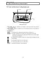
(9) Setting display:
Display part of this detector.
(10) Meas urement part:
Optical assembly, detector element and electric circuits are built- in.
(11) Lamp housing:
Lamp is located inside.
(12) Power supply part:
Terminal board for wiring, power fuse, power supply unit and
output board are built in.
(13) Power fuse:
A power fuse is mounted to the fuse holder.
Power fuse: Insertion type, 2A, time lag fusion type
(14) Terminal board:
For wiring of connection cable. Terminus screw size: M4.
5. Names and functions of component parts
D AT A
CH
SE L
C H/ ・
E N T
D A TA
CH
(1) Detector mounting
screw hole- 2
(2) Data display
wi ndow
(3) Door
(5) C onnection cable inlet (small)
(6) C onnection cable inlet (large)
(6) Manufacturing
nameplate
(8) Connector on l ight receiving side
(7) Connector on light projecting side
(11) Lamp
(9) Setting di splay
part
(14) Terminal board
(10) Measuring part
(12) Power suppl y part
(13) Power
supply
fuse
For preventing electric shock, make sure to turn the power supply off
before wiring.
W a rn i n g
!

