- 50 -
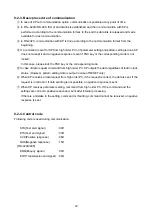
⑱
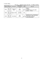
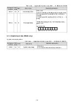
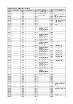
Operation status information
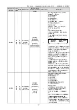
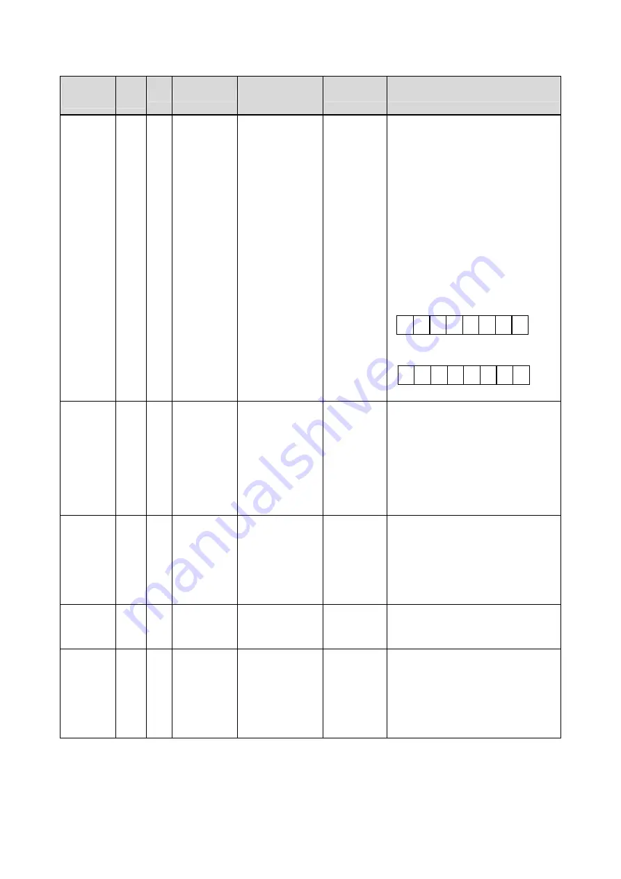
FNC code……Application function code, R/W……R: READ, W: WRITE
Reference
number
FNC
Code
R/W Data name
Setting range
(Communication
range)
Initial value
Remarks
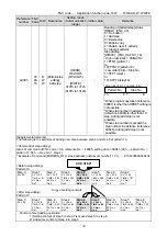
49501
03
06
16
R
W
W
Setting
screen mode
lock
(bit support)
0000h to 0967h
(0000h to 0967h)
0000h
(Normal
display)
[READ] (FNC_03)
0= Normal display
1= Lock (lock status) or NoDisp
(screen non display)
[WRITE] (FNC_06, FNC_16)
0= Normal display
1= Lock (lock status)
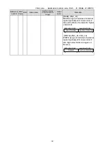
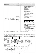
* READ/WRITE after relating bit 0 to
11 of 16 bits data to mode 0 to 11.
*Reading is indefinite and writing is no
effect to unallocated bit (mode) or
unshown mode.
Low order 8 bit
High order 8 bit
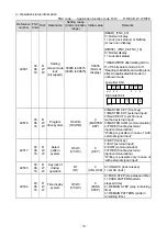
49516
03
06
16
R
W
W
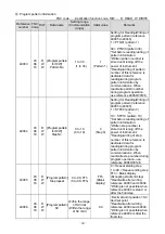
Program
drive system
0/1/2/3/4
(0/1/2/3/4)
0
(MASTER
KEY)
0=MASTER KEY (front key)
1=MASTER EXT (external input)
2=SLAVE EXT (synchronous
method external input)
3=MASTER COM (communication)
4=FREE (front key/external
input/communication)
*Writing is possible in case of 'with
external signal input'
49517
03
06
16
R
W
W
Select
pattern
system
0/1/2/3
(0/1/2/3)
0
(KEY)
0=KEY (font key)
1=EXT (external input)
2=COM (communication)
3=FREE (front key/external
input/communication)
*Writing is possible only in case of
'with external signal input'
49533
03
06
16
R
W
W
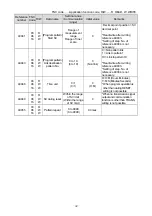
Key lock of
driving
operation
0/1
(0/1)
0
(UNLOCK)
0= UNLOCK (lock release)
1= LOCK (lock)
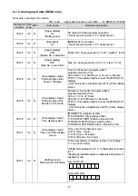
49534
03
06
16
R
W
W
Time display
system
0/1/2/3
(0/1/2/3)
0
(PASS
STEP)
0= PASS STEP (step elapsed time)
1= PASS PATTERN pattern
elapsed time)
2= REMAIN STEP (step remaining
time)
3= REMAIN PATTERN (pattern
remaining time)
mode
1
mode
5
mode
2
mode
0
mode
6
bit 7 6 5
2 1 0
mode
11
mode
8
bit 15
11 8


