12
11
Screen configuration and explanation
No.
Names
Explanations
1
Main Menu Bar
Various functions can be selected. Refer to the next page.
2
Alarm Area
and Highest
Temperature
Display alarm area in the thermal image. The place of the highest
temperature in the Alarm area is indicated with a
mark and its
temperature is displayed on the upper left of the thermal image.
3
Thermal Image
screen
Display a 2-dimensional thermal image based on temperature from each
pixel in a 48x47 array. The frame rate of the display is 3fps.
The coordinates of pixels displaying temperature values are (X=0, Y=0)
as the origin at the top-left and (X=47, Y=46) at the bottom-right.
4
Alarm Set Value
Display alarm value set by auto correct or manual correct.
5
Current Time
The current time of the PC is displayed.
6
Temperature Scale
Maximum and minimum values of the temperature scale being displayed
currently
To change values, click the up/down arrows or enter values from the
keyboard after clicking the box.
7
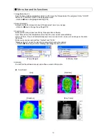
Color Palette
Color resolution is 256 colors. By clicking the color palette, the displayed
pattern of thermal image can be changed.
The default is Iron.
There are 4 pallets available. Iron, Rainbow, Gradation and Gray Scale.
Refer to the next page.
8
Thermal Image
Run/Stop
Run/Stop for communication
9
Temperature Value
and Coordinate of
the Pixel
The coordinate and temperature value selected by the cursor
are displayed.
10
Sensor ID
The setting and IP address of the sensor displaying the thermal image
are indicated.
11
Indicator for Alarm
from Sensor
The red/yellow colors are flashed when the alarm set on the sensor is
activated.
1
2
10
3
6
7
5
8
9
Origin (0,0)
4


