13
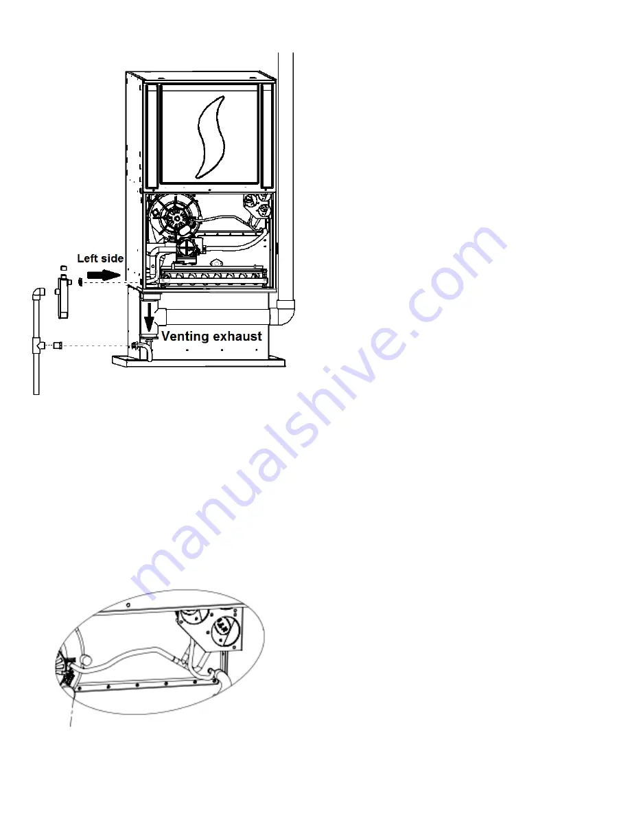
Figure 7 : Down flow orientation
4.3.2-
Downflow venting drainaged
All furnace with horizontal exhaust vent piping must have a drain tee
assembly and trap installed in the exhaust pipe as close to the furnace as
possible.
4.3.3-
Condensate box pressure switch
The 3/16 stub just beside the drain of the condensate box must be drilled
or cut open. The PVC tubing of the pressure switch -0.2 (nearest to the ID
blower) must be connected to this stub.
Figure 8 Condensate pressure switch
4.4- HORIZONTAL RIGHT ORIENTATION
4.4.1-
Horizontal right condensate drain connection
1.
Remove all PVC tubes from the ID blower, condensate box and
vent collector and block the stubs with furnished 5/8’’ & 1/2’’ black
caps.
2.
Remove the knock-outs from the bottom middle side of the
casing.
3.
Place the drain trap gasket on the drain trap.
4.
Screw in place the drain trap with 2 head tapping screws on the
side of the furnace.
5.
Install two 1/2
” black plastic cap on the stubs of the drain trap
inside the furnace.
6.
Connect a piece of 5/8’’ PVC tube to the bottom left of the
condensate box and route with an elbow to the drain trap.
7.
Install the drain trap on the bottom middle side, the three outlets
stubs of the drain trap toward the interior of the furnace.
8.
Connect the outlet drain from the drain trap to an additional
condensate piping in compliance with the local building codes or
to a condensate pump approved for use with acidic furnace
condensate.
NOTE :
The drain trap must be vertical.
Summary of Contents for c105-1-d
Page 20: ...20 Figure 16 Wiring diagram One stage PSC ...
Page 21: ...21 Figure 17 Two Stage PSC Furnace Control ...
Page 22: ...22 Figure 18 Two Stage ECM Furnace Control ...
Page 26: ...26 Figure 21 Direct venting Figure 22 Multi venting ...
Page 37: ...37 Figure 25 Part list 1 Stage PSC ...
Page 38: ...38 Figure 26 Part list 1 Stage PSC continued ...
Page 41: ...41 Figure 27 Part list 2 Stage PSC ...
Page 42: ...42 Figure 28 Part list 2 stage PCS continued ...
Page 45: ...45 Figure 29 Part list X13 ...
Page 46: ...46 Figure 30 Part list X13 continued ...
Page 49: ...49 Figure 31 Part list 2 Stage ECM ...
Page 50: ...50 Figure 32 Part list 2 Stage ECM continued ...


