Chapter 6 Key Functional Parameter Explanation In Detail 200 Series General Purpose Vector AC Drive
66
.
.
.
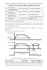
SP1
、
T0
、
T1
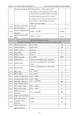
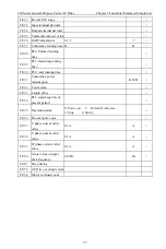
F6-00
F6-01
F6-02
F6-15
F6-16
Stage0
F6-18
Stage2
F6-17
Stage1
Output frequency
500ms Pluse
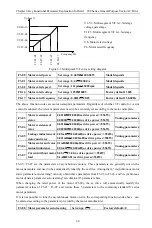
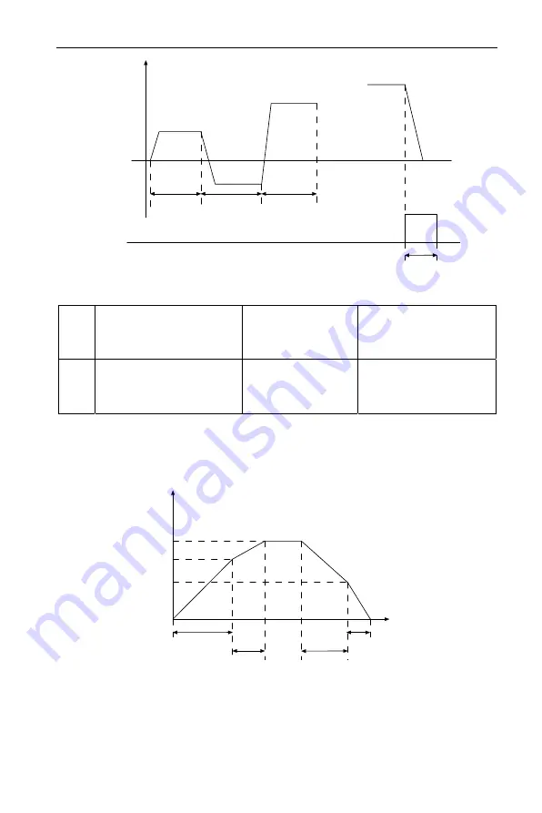
Figure 6-11 Simple PLC running diagram
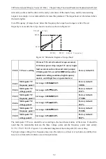
FA-28
Switch frequency point between
acceleration time 1 and
acceleration time 2
Factory default: 0.00Hz
Set range: 0.00Hz
~
3000.0Hz
FA-29
Switching frequency point
between deceleration time 1 and
deceleration time 2
Factory default : 0.00Hz Set range: 0.00Hz
~
3000.0Hz
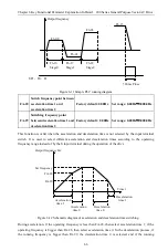
This function is valid when the acceleration and deceleration time is not selected by the input terminal
switch. It is used to select different acceleration and deceleration times according to the operating
frequency range instead of by the S input terminal during the operation of the drive.
Output frequency Hz
Set frequency
FA-28
FA-29
Acceleration
time 1
Acceleration
time 0
Deceleration
time 0
Deceleration
time 1
Time t
Figure 6-12 Schematic diagram of acceleration and deceleration time switching
During acceleration, if the operating frequency is less than FA-28, then select acceleration time 1; if the
operating frequency is bigger than FA-28, then select acceleration time 0. In the deceleration process, if
the running frequency is bigger than FA-29, the deceleration time 0 is selected, and if the running

