Page 30 Copyright CPS America Co., Ltd.
F. Modbus Card
I) INSTALLATION and CONNECTION:
CAUTION
The PCB SERMB is an accessory for the PV Inverter series
The installation has to be done with the unit OFF.
Don’t install the PCB is you see damaged on it.
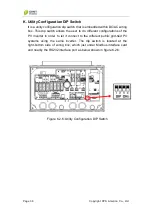
Before installing the PCB, it is necessary to configure the dip-switch as
indicate on following page. ( the factory setting are: mode 1, Baud-Rate
9600 )
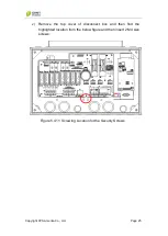
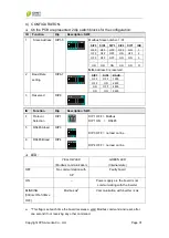
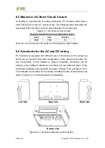
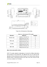
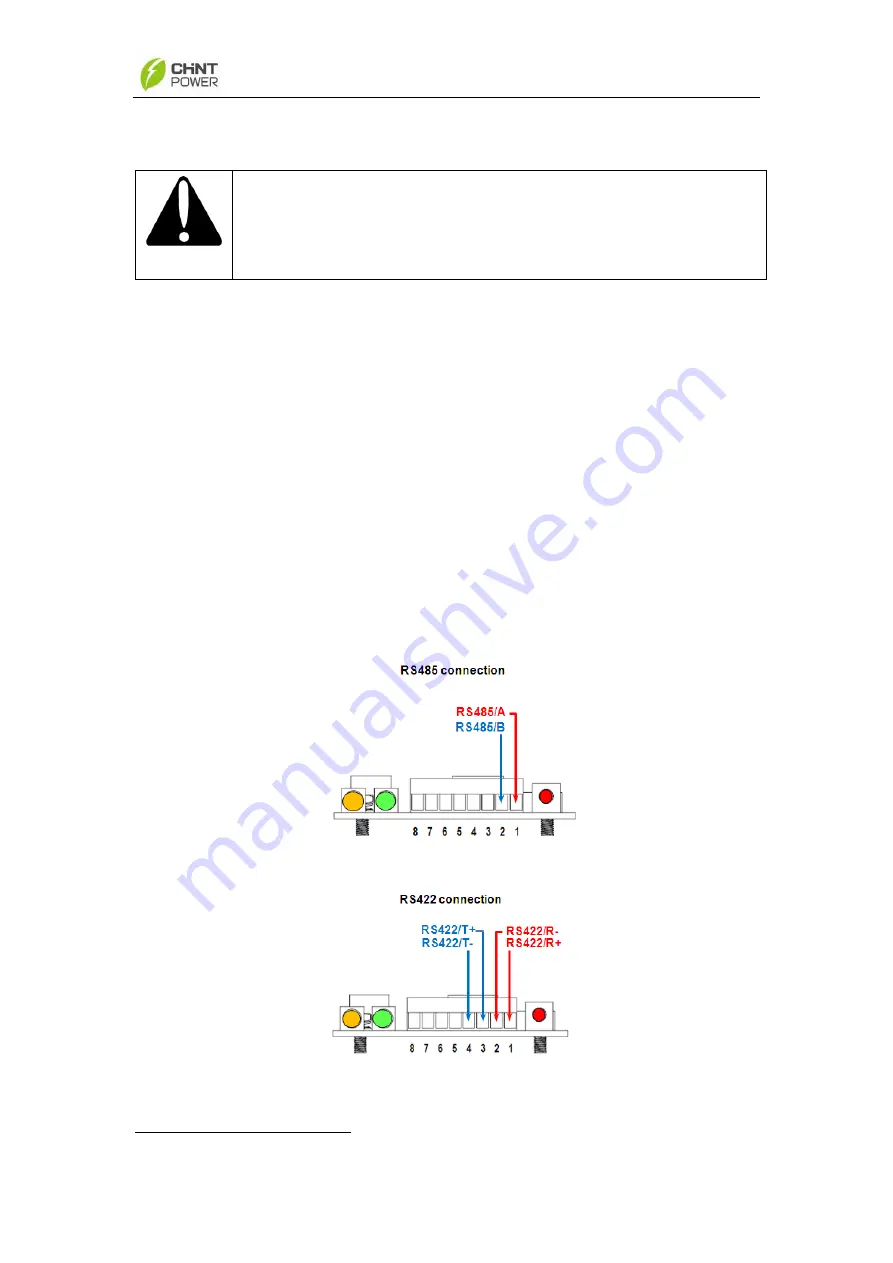
Connect the RS485/RS422 line to the connector on front panel, as show
on Fig 1.
It is suggested to use twisted cable section 0.22mm2, (AWG24)1.
If the RS485 is connected one PV Inverter only, or if the PV Inverter is the
last in the serial connection, it is necessary to set the SW3-4 to ON
position.
If in the RS422 is connected one PV Inverter only, or if the PV Inverter is
the last in the serial connection, it is necessary to set both SW3-3 and
SW3-4 to ON position.
Start the PV Inverter and verify the PCB.
Figure 6.2.4: RS 485/RS422 connections
1
The GND is available at Port 6 and Port 8 which refer to the internal GND system.


