background image


Page  34                                                                                        Copyright  CPS  America  Co.,  Ltd.


The  criterion  of  fuse  selection  can  be  calculated  by  a  standard  formula  in 

order to help the installer or service personnel to select the correct rating of 

fuse.   


The standard formula for DC Fuse Selection: 

Nominal Voltage of fuse must be 600V

DC


Rating and the fuse should be 

selected between 1.56 x Isc < I

N


Assume the maximum short circuit current (Isc) of the solar module used is 

4.85A. The rating of  the selected fuse must have a nominal current  greater 

than 1.25 times but less than 1.6 times the short circuit current as 

1.56 x Isc 

< I

N


Calculated by Standard Formula: 

A) 

4.85A x 1.56 = 7.56A   


B) 

Implemented the above result within 

1.56 x Isc < I

N


C)  The  calculation  result  will  be  7.56A  <  I

N

.  That  means  installer  must  to 

select a fuse rating that is greater than 7.56 A, but must lesser than 9.70 

A. Refer to the products information provided from Littelfuse factory, we 

are able to select KLKD008, 8A, 600V

DC

 DC as the protection fuse for 

the DC input side.     


IMPORTANT 

The  fuse  calculation  for  the  fuse  selection  is  referring  to  the 

requirements  (information)  that  had  been  indicated  within  the 

National Electrical Code(NEC), ANSI/NFPA 70.


To ensure trouble-free fuse protection, Eaton recommends using 

fuses  that  have  been  tested  by  Eaton.  The  specifications  for 

fuses from Littelfuse and KLKD series can be downloaded from 

www.littelfuse.com.   

It is important to follow the standard formula in order to select the 

proper  rating  of  fuse  for  DC  protection.  And  the  size  of  the  DC 

and AC  wiring must  to  meet with the required size of cables as 

description at chapter H) DC input terminal block and chapter J) 

AC output terminal block in the section 6.2. 


Summary of Contents for CPS SCE4

Page 1: ...CPS SCE Series Grid tied PV Inverter CPS SCE4 5 6 7KTL O US Installation and Operation Manual Version 1 1 ...

Page 2: ...wer com Service Hotline 855 584 7168 Address 700 International Parkway Suite 102 Richardson Texas Zip Code 75081 SHANGHAI CHINT POWER SYSTEMS AMERICA CO LTD All rights reserved Specifications and designs included in this manual are subject to change without notice CHINT POWER 2013 06 MKT ...

Page 3: ...r 17 6 Wiring Box Overview 26 6 1 Hardware Structures 26 6 2 Hardware Functioning 26 6 3 Maximum AC Short Circuit Current 38 6 4 Knockouts for the AC and DC wiring 38 7 Connecting the PV Inverter 42 7 1 DC Wire Connections 42 7 2 AC Wire Connections 46 8 LCD Display and Function Structure 53 8 1 First Level Display Menu 53 8 2 Second Level Display Menu 54 8 2 1 Daily Weekly and Monthly Energy Disp...

Page 4: ...erter or simply Inverter This PV Inverter is a highly reliable product due to its innovative design and perfect quality control Such an Inverter is used in high demand grid tied PV systems If you encounter any problems during installation or operation of this unit first check this manual before contacting your local dealer or supplier Instructions inside this manual will help you solve most instal...

Page 5: ...e and other local regulations to meet the requirements of electrical installation in the United States For the electrical installation in Canada inverter installation must be completed in accordance with applicable Canadian standards Safety Instructions This manual contains important safety instructions to minimize the hazards to people and equipment Not following the procedures and practices corr...

Page 6: ...njury if not avoided IMPORTANT Important indicates important and useful information that the user should know about the system ESD Protection Risk of electric shock can occur when qualified service personnel are dealing with the electrical components within the PV Inverter such as wiring box An ESD glove should be worn during the wiring operation fuse replacement and component installation Tool Eq...

Page 7: ...ation relating to other equipment installed in the PV system The following safety instruction should be followed WARNING It is necessary that only qualified personnel conduct the installation and operation of the PV Inverter Otherwise risk of damage to or destruction of part or all of the Inverter and or other equipment connected to the Inverter or personal injury due to improper installation proc...

Page 8: ...urposes other than for which it was designed The Inverter has been used beyond its stated specifications operating parameters and application Acts of third parties atmospheric discharges excess voltage chemical influences natural wear and tear and for loss and damage in transit Improper testing operation maintenance adjustment repair or any modification of any kind not authorized in writing by the...

Page 9: ...ltage out 208 240 277 Vac Wide MPPT voltage operating range 105 500V Integrated NEC compliant wire raceway Integrated PV system AC DC disconnect switch 4 branch circuit rated Negative and Positive fused inputs Performance Monitoring Package LCD display with side pushbutton for nighttime monitoring NEMA 3R enclosure Meets UL1741 standard ...

Page 10: ...fficient irradiation they will generate DC power First the DC will be fed to the PV Inverter via DC distribution unit Then the Inverter converts the DC to AC and feeds AC to the Public Grid via the AC distribution unit The AC power can be used directly by the local load or it can be sold to your energy supplier The following figure shows the general picture of a grid tied PV System Figure 4 1 1 Ge...

Page 11: ...is compatible with the local electric distribution network also called the public grid The CPS grid tied PV Inverter is designed with a transformer less topology Therefore CPS grid tied PV Inverters will not be suitable with PV modules that are required to have the negative or positive polarity of PV modules connected to the ground For such application please contact the supplier before proceeding...

Page 12: ...Page 9 4 3 Dimensions and Weight Figure 4 3 1 Dimensions of PV Inverter Table 4 3 1 Product weight in the package Inverter Model CPS SCE4KTL O US CPS SCE5KTL O US CPS SCE6KTL O US CPS SCE7KTL O US Net Weight lbs 86 90 4 101 4 101 4 ...

Page 13: ...s C Control Buttons They are three control buttons available to switch between each display menu and configure the settings for the LCD D DC AC Disconnect Switch It is a built in disconnect switch that is used to disconnect both the DC input and AC output power to and from the PV inverter E Hand Grip Area It is a carrying area that is used to lift up the PV Inverter For the lifting two people are ...

Page 14: ...ill light up in green when the feed in DC voltage from PV array reaches the minimum operating voltage for the PV Inverter B Fault LED Indicator It is a red LED indicator that lights in red when the PV Inverter has a fault during startup or operating period C Communication LED Indicator It is a Green LED indicator that lights and flashes in green when there is a communication device connected and w...

Page 15: ...lay menu the user can hold the enter control button for more than two seconds until LCD displays a Lock text To release the user can presses the same control button for another two seconds again in order to release menu from the lock mode C Down Control Button The down control button is used to advance the display menu in the opposite direction to the up control button D Liquid Crystal Display LCD...

Page 16: ...kage The 3 Accessory Box contains items listed below Items Q ty Purpose Figure User s Manual 1 Installation and Operation Manual Mounting Anchor 6 For bracket installation Screw M4 6 Security Screw M4 2 For security locking to Inverter Terminal Connector See For AC DC Wires Table 5 1 2 Items in the accessory box Terminal Connectors of AC DC wires are provided for Each Inverter Model Table 5 1 3 Nu...

Page 17: ...ue to the weight of the inverter it is recommended at least 2 people lift the PV Inverter from the packing and also for the mounting the PV Inverter on the wall CAUTION It is important to use the correct lifting point to lift the PV Inverter from the packing as any improper carrying and moving could result in serious injury or damage the unit Warning Any modification of the PV Inverter is not perm...

Page 18: ...trical components that are used for power conversion and the wiring box contains the electrical components that are used as the connection points for DC input voltage and AC output voltage as required by the NEC Figure 5 3 1 PV Inverters Structure CPS grid tied PV Inverter can be identified by the name plate The name plate indicates general electrical information of the product as shown in Figure ...

Page 19: ... in figure 5 3 4 This warning label is used to indicate all important notices that shall be known When you are dealing with the general utility system and DC generator read and follow all notifications from the warning label as a reminder in order to prevent any electric shock that can happen during the configuration period Figure 5 3 4 Warning Label Plate ...

Page 20: ...emperature between 20 and 45 C IMPORTANT It is important not to install the CPS grid tied PV Inverter under direct sunlight because the exposure of direct sunlight may cause an internal heating and also a reduction of output power which is known as derating protection B Select a wall or solid vertical surface which is strong enough to support the inverter ...

Page 21: ...cted location has a sufficient space for air flow C The PV Inverter requires an adequate cooling space for heat dispersal Therefore the PV Inverter must have sufficient clearance for the air flow as illustrated below Figure 5 4 2 Required Clearance Space IMPORTANT The NEC requires that the DC disconnect should be mounted between 3 ft 6 5 ft from the ground if the PV Inverter will be used as the st...

Page 22: ...r orientation for the PV Inverter is very important The PV Inverter should be installed in a vertical position In order to avoid heat dissipating issues ensure there are no any obstacles located or installed near by the PV Inverter Figure 5 4 3 Installing Position and Location ...

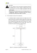
Page 23: ...ay from living or working areas where noise could be a concern E Fix the bracket by using outer mounting holes i A rectangular shaped mounting bracket that shipped with the PV Inverter is able to be used with all types of walls such as stone wall brick wall or wooden wall but it is more important to ensure the wall that is selected will be able handle with the weight of PV Inverter specifically th...

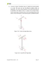
Page 24: ...oints as appropriate The corner screwing points or the central screwing point as illustrated in the figures below To secure the mounting bracket mark 6 outer holes on the wall drive in the 6 mounting anchors then screw in the 6 M4 screws to each screwing point as illustrated below Figure 5 4 5 Corner screwing fixing mode Figure 5 4 6 Central Point Fixing Mode ...

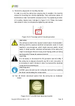
Page 25: ...w i Hook up the PV Inverter by aligning the opening of rear side enclosure and place the PV Inverter into each targeted wedge points of the mounting bracket as illustrated below Figure 5 4 7 Install PV Inverter into mounting bracket IMPORTANT Check the mounting bracket again before the PV Inverter is hung on the bracket It is recommended to have least 2 service personnel for this procedure due to ...

Page 26: ... the exposed electrical components under in moist weather is very dangerous which might cause an electric shock easily In dusty weather electrical components of the wiring box might be damaged if there is heavy dust floating within air during serving period Please be aware and avoid CAUTION It is necessary to disconnect the DC generator and AC Utility if the wiring box is already wired with any DC...

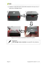
Page 27: ...Co Ltd iv Unfasten 2 pieces M4 and 4 pieces M5 screws from the top cover of wiring box as illustrated below Figure 5 4 10 Remove the screws of DC AC Wiring Box Screwdriver A M5 hexagon head screwdriver is required for the procedure ...

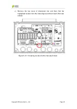
Page 28: ... America Co Ltd Page 25 v Remove the top cover of disconnect box and then find the highlighted location from the below figure and then insert 2 M4 size screws Figure 5 4 11 Screwing Location for the Security Screws ...

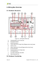
Page 29: ... Input side B DC bypass terminal C DC AC Disconnect D 2 fuse holder for AC Output Side Shipped with dummy fuses E Modbus Card F 8 fuse holders for DC Input Shipped with dummy fuses G DC input terminal H Protection MOV for AC Output side I AC output terminal J AC Utility configuration dip switch K RS232 Interface Port 6 2 Hardware Functioning ...

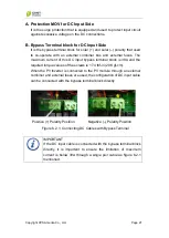
Page 30: ...ss terminal block is 38A and the required torque values of the screws is 17 4 lbf in 20 Kgf cm When the PV Inverter is connected to the PV module through an external combiner and external fuses are used the configuration of DC input cable can be connected with the bypass terminal block directly Positive Polarity Position Negative Polarity Position Figure 6 2 1 Connecting DC Cables with Bypass Term...

Page 31: ...e specification of external breakers or fuses shall meet the recommended ratings listed in the following table II If there is no external AC breaker or fuse protector installed it is recommended to have AC protection fuses installed to the AC side And the AC fuse that can be selected from the recommended list as below table indicates To ensure the rating of the fuses that are used for the each mod...

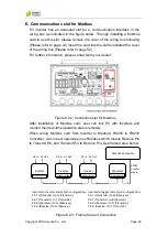
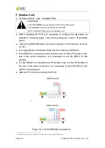
Page 32: ...monitor their real time operation status remotely When wiring Modbus card from Inverter to Modbus RS485 to RS232 Converter we connect opposite pins of Modbus which means Receive Pin to Transmit Pin and Transmit Pin to Receive Pin See framed area below Figure 6 2 3 Framed area of Connection Inverter DC In AC Out Converter Inverter DC In AC Out Inverter Modbus RS485 DC In AC Out Remote Computer RS23...

Page 33: ...5 RS422 line to the connector on front panel as show on Fig 1 It is suggested to use twisted cable section 0 22mm2 AWG24 1 If the RS485 is connected one PV Inverter only or if the PV Inverter is the last in the serial connection it is necessary to set the SW3 4 to ON position If in the RS422 is connected one PV Inverter only or if the PV Inverter is the last in the serial connection it is necessar...

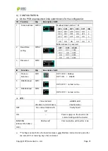
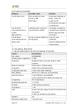
Page 34: ...d DIP8 1 2 3 4 5 6 7 8 ON DIP ID Function Dip Description SW3 4 Protocol Selection DIP1 DIP 1 OFF Modbus DIP 1 ON RS485 5 RS485A load DIP3 1 2 3 4 DIP ON DIP 3 OFF no load on line DIP 3 ON 120Ohm load on the line 6 RS485B load DIP4 1 2 3 4 DIP ON DIP 4 OFF no load on line DIP 4 ON 120Ohm load on the line LED YELLOW LED Modbus communication GREEN LED Internal state OFF No communication with AP Faul...

Page 35: ...l resistor setting Verify the dip switch setting IV TECHNICAL FEATURES See the table below for the technical features of the board Feature Specification Part number S0SER02MB Insulated power supply SELV 12VDC Description Modbus Protocol conversion board for Solar inverters Modbus commands suppurated 0x04 single or multiple reading 0x06 for the commands sending Configurable baud rate 1200 2400 4800...

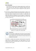
Page 36: ...ports and others fuse holders are equipped for the four negative polarity ports Therefore there are supports to have eight fuse folders total to the DC side as shown in figure 6 2 5 Figure 6 2 5 Location of DC Fuses Holders IMPORTANT The PV Inverter is shipped with a dummy fuse in the fuse holder It is necessary to select the proper series fuse depending with the solar modules that are used Remove...

Page 37: ...installer must to select a fuse rating that is greater than 7 56 A but must lesser than 9 70 A Refer to the products information provided from Littelfuse factory we are able to select KLKD008 8A 600VDC DC as the protection fuse for the DC input side IMPORTANT The fuse calculation for the fuse selection is referring to the requirements information that had been indicated within the National Electri...

Page 38: ...sed to connect AC cables from the utility system also known as the public grid Each model of the Eaton grid tied PV Inverter requires different sizes of AC cables The following table indicated the cable size and torque values that are required for position 1 pole position 2 pole position 3 pole in the AC terminal block when a 208 grid tied PV system is applied with the PV inverter Table 6 2 3 Stan...

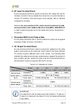
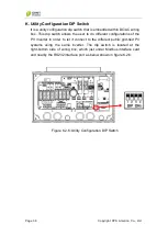
Page 39: ...ows the user to do different configurations of the PV Inverter in order to let it connect to the different public grid tied PV systems using the same inverter The dip switch is located at the right bottom side of wiring box which just under Modbus interface card and nearby the RS232 interface port as below shown in figure 6 2 6 Figure 6 2 6 Utility Configuration DIP Switch ...

Page 40: ...ll PV Inverters are integrated with a DB9 socket for the RS232 interface as a built in interface in the wiring box The pin assignment of DB9 socket is shown in the table below Figure 6 2 7 RS232 Interface Pin Assignment IMPORTANT The RS232 interface and Modbus card share the same communication port thus they are not able to work together at the same time Before using the RS232 interface please rem...

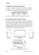
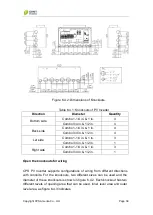
Page 41: ...ing the output breaker 6 4 Knockouts for the AC and DC wiring PV Inverters is equipped with different size of knockouts in the wiring box which can be used for the cable configuration of DC side and AC side For the convenience of the installer or system integrator knockouts can be utilized in four different directions and there are two different sizes of the knockouts available to be selected as s...

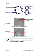
Page 42: ...bo 1 1 4 in 1 in 3 Combo 3 4 in 1 2 in 1 Right side Combo 1 1 4 in 1 in 3 Combo 3 4 in 1 2 in 1 Open the knockouts for wiring CPS PV Inverter supports configurations of wiring from different directions with conduits For the knockouts two different sizes can be used and the diameter of these knockouts is shown in figure 6 4 2 Each knockout has two different levels of opening area that can be used i...

Page 43: ...nts of inner level Figure 6 4 5 Knocking points of outer level Tools A M4 size slotted screwdriver and hammer are required for the opening procedure of knockouts Inner level area Outer level area Upper Knocking Point Lower Knocking Point Right hand side Knocking Point Left hand side Knocking Point 0 5 0 75 1 25 1 ...

Page 44: ... 4 7 Knocking point of outer level IMPORTANT Be sure to follow all instructions to strike knock out the opening hole by the proper procedures Otherwise the opening area of knockout can be easily damaged if improper tools are used or any improper procedures are done for the opening please beware 1st Step Use tools to target upper strike point and knock it 2nd Step Use tools to target bottom strike ...

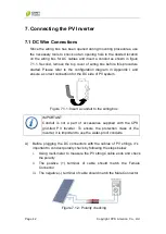
Page 45: ...t connection for the DC side of PV system Figure 7 1 1 Insert a conduit to the wiring box A Before plugging the DC connectors with the cables of PV strings it s important to conduct polarity check by following the steps below i Using multi meter to measure the PV strings cable ends and check the polarity ii The positive terminal of cable should match the Female Connector iii The negative terminal ...

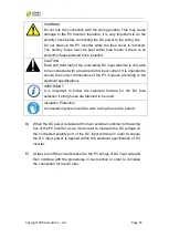
Page 46: ...e a multi meter to measure the DC input voltage that is generated from the PV modules It must not exceed 600VDC IMPORTANT The CPS grid tied PV Inverter is designed with a transformer less topology It is recommended NOT connecting the Inverter with the PV modules that require positive or negative polarity to ground And it is also necessary to have a circuit breaker or fuse switch installed between ...

Page 47: ...arity cable in the DC terminal by a screwdriver with the required torque value v Connecting DC negative polarity cable to the DC negative pole terminal in the wiring box vi Tighten the DC negative polarity cable in the DC terminal by a screwdriver with the required torque value vii Double confirm the DC cable from the DC terminal in order to ensure all the DC cables have been tighten firmly in pro...

Page 48: ...he correct connections of the PV modules according to the electrical specifications IMPORTANT It is important to follow the standard formula for the DC fuse selection if string fuses are planned to be used Insulation Protection An insulation glove should be worn during the service period D When the DC power is delivered from an external combiner to the wiring box of the PV Inverter use a multi met...

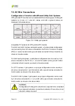
Page 49: ...e L2 location as shown in the above table For 240V split grid system a split phase configuration can be used by 3 AC wires connected to the PCC s L1 L2 and N location and a ground cables connected to the N location as shown in the above table For 277V 3 phase Y grid system a wye type configuration can be used by 2 AC wires connected to L1 and N locations with a ground cables connected to the N loc...

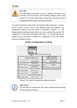
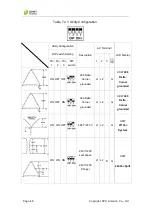
Page 50: ... the PV Inverter can be used in the different utility grid systems The configuration setting of this dip switch is described in figure 7 2 1 The following tables described the functions that can be enabled through the PIN configuration on the utility configuration dip switch It is recommended that a qualified service personnel complete the configuration of this DIP switch during the installation p...

Page 51: ...y DIP switch Setting 1 2 3 Pin 1 Pin 2 Pin 3 DIP switch ON OFF OFF 208 Delta Corner grounded L1 L2 G XKW 208 Delta Corner grounded ON OFF ON 240 Delta Corner grounded L1 L2 G XKW 240 Delta Corner grounded ON ON OFF 480 Y 277 V L1 L2 G XKW 277Vac System ON ON ON 240V 120V split phase 240V 120V Stinger L1 L2 N G XKW 240Vac Split ...

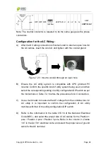
Page 52: ...nd of utility system being used and then select the corresponding setting of utility configuration DIP switch as per the instructions in Table 7 2 1 before the procedures for AC connection C Use a multi meter to measure the AC voltage from the combiner box for AC utility It is important to confirm the configuration of AC utility matches with that of the utility configuration DIP switch D Refer to ...

Page 53: ...1 Kgf cm Terminal block labeled with G Admissible conductor size 10AWG Torque value 15 6 lbf in 18 Kgf cm 33 1 lbf in 38 1 Kgf cm IMPORTANT The selection for the AC cable size and required torque values for the Position 1 Position 2 Position 3 is referred to the table 310 16 in the National Electrical Code NEC E Connect the AC cables with PV inverter by inserting them through the conduits into wir...

Page 54: ...e ground symbol pole On the other hand please ensure the setting of the AC DIP switch has been set correctly with the applied grid system Figure 7 2 6 Connect the AC Cables to Correct Positions H Tighten the screws for the AC cables with the required torque values as listed in the Table 7 2 2 Then turn on the circuit breaker from the utility panel or switchboard and use a multi meter to measure wh...

Page 55: ...Page 52 Copyright CPS America Co Ltd J Lastly reinstall the top cover of wiring box by tightening 2 M4 and 4 M5 screws as shown below Figure 7 2 7 Reinstall the top cover of wiring box ...

Page 56: ...nu Display date and time of the current day DC Voltage and DC Current Menu Display the DC voltage and DC current from the PV array AC Voltage and AC Current Menu Display the output AC voltage and AC current Frequency and Output Power Display the AC frequency and the instant output power of the unit Nominal Power and Grid System Menu Display the nominal power of the PV Inverter and voltage of the A...

Page 57: ... Menu It is a menu that will display the output energy for the past 52 weeks E Month Display Menu It is a menu that will display output energy for the past 12 months EXIT Display Menu It is a menu that is used to return back to Etoday menu the level 1 display menu Etoday Energy E Day Date Output Energy E Week EXIT Week Output Energy Month Output Energy Press Enter Press Enter Press Enter Press Ent...

Page 58: ... and time of the PV Inverter The Enter button is used to change between different units of time and the direction buttons are used to adjust the value of the unit such as year month day hour minute and second IMPORTANT Operational data will be recorded by the date and hour Therefore it is important to ensure the time of inverter is adjusted correctly Date Hour Adjusting Year Press Enter Press Ente...

Page 59: ... and internal cooling fans are not working properly 2 FAN1 Lock is the second kind of failure message when the external cooling fan is not working properly 3 FAN2 Lock is the third kind of failure message when the internal cooling fan is not worked properly If FAN1 Lock is indicated on the CPS SCE6KTL O US and CPS SCE7KTL O US models please check whether there is any obstacle stopping blocking the...

Page 60: ...cedures describes how to change the cooling fan please read and understand all procedures before doing so A Switch off the DC AC disconnect switch and wait for at least three minutes to discharge the stored energy in the PV inverter Figure 9 1 1 Turn off DC AC switch B Unfastening all screws located in each corner as highlighted in figure 9 1 2 After the screws are removed take off the top cover o...

Page 61: ...the cooling fan as shown in Figure 9 1 3 Figure 9 1 3 Disconnect the power cables of the cooling fan D Replace with a new cooling fan by connecting its power cable to PV Inverter Then re tighten the 4 screws at the top cover E Switch on the DC AC disconnect switch to complete the fan replacement procedure ...

Page 62: ...sary not to remove the top cover of wiring box until 3 minutes after DC AC disconnect switch is turned off It is necessary to turn off the external DC AC breakers if they exist Otherwise it is important to disconnect all the PV modules and AC utility connections before the service of fuse replacement The PV Inverter must be disconnected from all sources of power supply Refer service to only qualif...

Page 63: ...m the recommended list of brands and rating as described in the DC and AC protection chapters in section 6 2 of this manual Figure 9 3 3 Install a new fuse D Install the fuse cover with the new fuse into the correct fuse holder as shown in figure 9 3 4 It is important to ensure the fuse cover is inserted tightly into fuse holder in order to complete the fuse replacement and re installation procedu...

Page 64: ...irs 4 4 4 4 Max DC current 19 A 26 A 32 A 37 A Max Input Current per String 20A 20A 20A 20A DC insulation resistance 2 2M DC Disconnection Type Switch Output AC Nominal AC power 240Vac 277Vac 4000W 5000W 6000W 7000W Nominal AC power 208Vac 3800W 4600W 6000W 7000W Max AC power 240Vac 277Vac 4000W 5000W 6000W 7000W Max AC power 208Vac 3800W 4600W 6000W 7000W Grid Connection Type Single phase 240V Sp...

Page 65: ...A 22 5A 28 5A 33 2A Max AC current 7 277Vac system 16 4A 20 5A 24 6A 28 7A System Topology Transformerless Max Efficiency 97 5 CEC efficiency 97 Stand by Night Consumption 8 7W 0 2W Environment Protection Degree NEMA 3R Cooling Forced air cooling Operating Humidity 0 95 non condensing Operating Altitude 6562ft 2000m without derating Operating temperature range 9 25 50 5 Regulation range 244 305Vac...

Page 66: ...Display and Communication Display LCD LED Communication RS232 Modbus Mechanical Data Dimensions WxHxD 17 0x33 4x8 4in 434x850x213mm Weight 86lbs 39kg 90lbs 41kg 101lbs 46kg 101lbs 46kg Safety Safety and EMC Standard UL1741 2010 CSA C22 2 No 107 1 01 FCC PART15 Class B Grid Standard IEEE1547 2003 IEEE1547 1 2005 ...

Page 67: ...voltage is higher than 150V inverter is waiting for feeding to the grid 2 After Startup Input voltage range is at 80 100V Check Grid Checking xxxS When PV voltage 150V inverter is checking grid conditions Feeding Grid Normal Inverter is feeding power to the grid FLASH FLASH FLASH Firmware II Monitoring Parameter Messages Operation Condition Messages Descriptions Instantaneous Output Power Pac xxxx...

Page 68: ...ncy No Utility No Utility Utility is not available Input Voltage too High PV over voltage Input voltage higher than the 600V Ground I Fault Ground I Fault Leakage current on ground conductor is too high V Inverter Fault Messages Operation Condition Messages Descriptions Consistent Fault Consistent Fault The readings of 2 microprocessors are not consistent It could be caused by CPU and or other cir...

Page 69: ... A Isolation Fault Conditions The resistance between the PV or PV and grounding is outside the permissible range 2MΩ Corrective Actions Restart the inverter again If fault still occurs after the unit is restarted contact the system installer immediately Ask the system installer to check if the PV Inverter and PV Modules are properly insulated throughout the solar system B Grid Fault Conditions The...

Page 70: ...ns of the PV Inverter Check the AC fuses of the PV Inverter If failure remains disconnect the PV Inverter and contact the system installer D PV Over Voltage Conditions DC voltage fed by the PV module is higher than permissible range 600Vdc Corrective Actions Disconnected PV modules immediately Check the configuration of the strings for the PV modules and ensure the maximum input voltage is lower t...

Page 71: ...nt cooling fan and remove the obstacle if any If the top fan is not functioning it may be replaced as per the instructions described in section 9 1 If fault remains disconnect the PV Inverter and contact the inverter installer C Over Temperature Conditions The internal temperature is higher than normal value Corrective Actions Disconnect PV Inverter for a period of time 30 minutes and then restart...

Page 72: ...access problem Corrective Actions Restart the PV Inverter If fault remains disconnect the PV Inverter and contact the inverter installer G SCI failure Conditions Communication between the inside MCU is abnormal Corrective Actions Restart the PV Inverter If fault remains disconnect the PV Inverter and contact the inverter installer H High DC bus Conditions The DC BUS inside is higher than expected ...

Page 73: ...verter If fault remains contact the inverter installer to check the grounding of the PV Inverter If the fault remains disconnect the PV Inverter and contact the inverter installer J Damp Fail Condition The resistance stick is working outside the permissible range Corrective Actions Restart the PV Inverter If fault remains disconnect the PV Inverter and contact the inverter installer ...

Page 74: ...ht CPS America Co Ltd Page 71 12 Power Curve Allowable Output Power vs String Voltage as shown below CPS SCE4KTL O US CPS SCE5KTL O US CPS SCE6KTL O US CPS SCE7KTL O US Figure 12 1 1 Line loss vs cable length ...

Page 75: ...Page 72 Copyright CPS America Co Ltd Appendix Configuration of Wiring Box ...

Reviews: