BZMJ Series Self-healing Low Voltage Shunt Capacitors
03
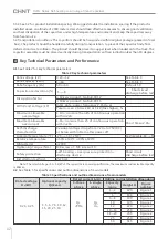
Table
3
(
continue
)
4
.
3
The
capacitors
are
placed
in
the
capacitor
compensation
cabinet
which
should
provide
the
following
protection
measures
.
See
Table
4
for
details
.
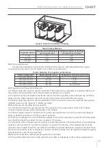
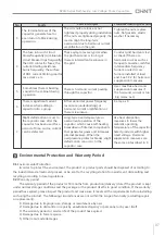
Table
4
Capacitor
protection
measures
in
cabinet
Protective
characteristics
Name
and
function
of
support
devices
Typical
models
Transient
overvoltage
protection
Zinc
-
oxide
surge
arrestor
or
surge
protector
FYS
-
0
.
28
or
NU6
-
2
Transient
overcurrent
protection
Capacitor
dedicated
contactor
,
current
limiting
reactor
,
or
smart
compound
switch
with
zero
-
cross
detection
.
CJ19
,
XD1
or
ZCK
Steady
stage
overvoltage
protection
Generally
,
compensation
controller
can
provide
overvoltage
protection
.
NWK1
-
G
,
NWKL1
Steady
stage
overcurrent
protection
Thermal
relay
or
capacitor
switch
with
overcurrent
protection
function
.
JR36
or
ZCK
Short
circuit
protection
Choose
fast
acting
fuse
for
short
circuit
protection
.
For
capacitors
with
capacity
<
30kvar
,
user
can
use
miniature
circuit
breaker
for
short
circuit
protection
.
For
capacitors
with
capacity
≥
30kvar
,
miniature
circuit
breaker
is
not
recommended
.
RT36
or
NT00
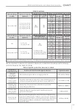
Rated
voltage
U
N
(
kV
)
Rated
voltage
U
N
(
kV
)
Optimal
capacity
Qc
(
kvar
)
Optimal
capacity
Qc
(
kvar
)
Rated
current
I
N
(
A
)
Rated
current
I
N
(
A
)
Outline
and
installation
dimensions
Outline
and
installation
dimensions
3
-
three
phase
1
-
single
phase
Capacity
range
Capacity
range
Height
H
Height
H
Figure
number
Figure
number
0
.
4
,
0
.
45
,
0
.
48
1
,
3
,
4
,
5
,
6
,
7
.
5
,
8
,
10
,
12
,
14
,
15
,
16
,
18
,
20
,
24
,
25
,
30
,
35
,
40
,
45
,
50
,
60
1
~
5
95
Figure
1
6
~
8
120
Figure
1
10
140
Figure
1
12
~
16
190
Figure
1
18
~
20
220
Figure
1
22
~
25
220
Figure
2
28
~
32
250
Figure
2
35
~
40
250
Figure
3
45
~
60
315
Figure
3
3YN
split
-
phase
compensation
capacitor
0
.
4
5
,
7
.
5
,
10
,
15
,
20
,
25
,
30
Y
refers
to
star
connection
,
N
refers
to
null
line
lead
out
.
5
~
7
.
5
140
Figure
2
10
195
Figure
2
14
~
16
250
Figure
2
20
295
Figure
2
25
~
30
315
Figure
3
0
.
45
,
0
.
48
,
0
.
525
5
,
7
.
5
,
10
,
15
,
20
,
25
,
30
5
~
7
.
5
140
Figure
2
10
195
Figure
2
14
~
16
220
Figure
2
20
250
Figure
2
315
Figure
3
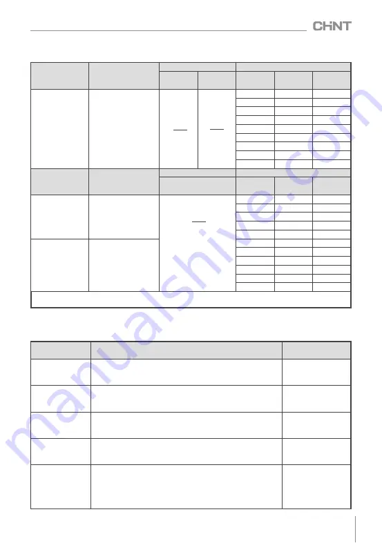
Note
:
The
dimensions
of
0
.
525
kV
,
0
.
69kV
,
0
.
75
kV
,
0
.
86
kV
,
1
.
2
kV
single
phase
products
may
be
different
from
those
in
the
table
,
please
refer
to
the
real
products
.
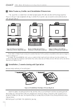
See
the
outline
and
installation
dimensions
in
this
manual
for
the
figure
number
of
outline
and
installation
dimension
drawings
.
Qc
√
3U
N
Qc
U
N
Qc
√
3U
N
25
30
Figure
3
250

