

05
6
.
3
Wiring
requirements
The
capacitors
should
be
connected
by
stranded
soft
conductors
,
with
pressed
dedicate
copper
connecting
lug
.
See
Table
6
for
the
selection
of
conductor
sectional
area
.
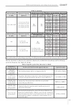
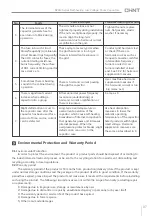
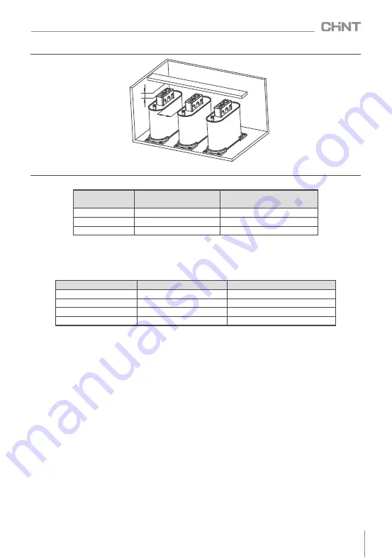
Capacity
(
kvar
)
Minimum
installation
spacing
S1
(
mm
)
Safety
distance
at
the
top
of
capacitors
S2
(
mm
)
1
~
20
30
≥
50
22
~
32
50
≥
50
35
~
60
80
≥
50
Rated
voltage
(
kV
)
Rated
capacity
(
kvar
)
2
Conductor
sectional
area
(
mm
)
0
.
4
,
0
.
45
,
0
.
525
≤
10
4
.
0
0
.
4
,
0
.
45
,
0
.
525
12
~
20
6
.
0
0
.
4
,
0
.
45
,
0
.
525
24
~
32
10
.
0
0
.
4
,
0
.
45
,
0
.
525
35
~
60
16
.
0
or
25
.
0
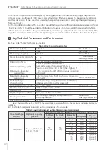
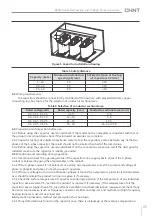
Figure
5
Capacitor
installation
drawing
Table
5
Safety
distance
6
.
4
Preparation
and
inspection
before
use
6
.
4
.
1
Before
using
the
capacitor
,
user
should
check
if
the
model
on
the
nameplate
is
consistent
with
that
of
the
product
.
User
should
also
check
if
the
included
accessories
are
complete
.
6
.
4
.
2
Capacitor
testing
:
Use
digital
capacitance
meter
to
test
the
capacitance
value
between
any
of
the
two
phases
of
the
3
-
phase
capacitor
,
the
result
should
not
be
smaller
than
half
of
the
rated
value
.
6
.
4
.
2
Before
using
the
capacitor
,
user
should
check
if
all
the
connections
are
secure
and
if
the
dust
guard
is
installed
,
make
sure
the
capacitor
is
reliably
grounded
.
6
.
5
Monitoring
and
recording
during
operation
6
.
5
.
1
User
should
check
the
operating
status
of
the
capacitors
on
a
regular
basis
,
check
if
the
3
-
phase
current
is
balanced
by
using
the
amperemeter
in
the
cabinet
.
6
.
5
.
2
If
the
3
-
phase
current
is
not
balanced
,
use
clamp
on
amperemeter
to
test
the
current
and
voltage
of
phase
A
,
phase
B
and
phase
C
of
each
group
of
capacitors
.
6
.
5
.
3
If
there
is
voltage
but
no
current
between
phases
,
it
means
the
overpressure
protector
is
disconnected
,
user
should
maintain
the
product
in
time
or
replace
it
if
necessary
.
6
.
5
.
4
Check
the
surface
temperature
of
capacitor
case
during
operation
,
if
the
temperature
of
any
individual
capacitor
case
exceeds
65
℃,
maintain
the
product
or
replace
it
if
necessary;
if
the
temperature
of
all
the
capacitor
cases
is
higher
than
65
℃,
take
effective
ventilation
and
heat
dissipation
measures
and
check
if
any
harmonic
source
device
(
such
as
frequency
converter
,
rectifier
and
inverter
,
and
medium
and
high
frequency
heating
furnace
)
is
used
at
user
load
end
.
6
.
6
Operation
procedure
,
method
and
precautions
for
shut
down
6
.
6
.
1
If
any
deformation
is
found
on
the
capacitor
case
,
there
is
oil
leakage
or
the
reactive
compensation
Table
6
Selection
of
conductor
sectional
area
S2
S1
BZMJ Series Self-healing Low Voltage Shunt Capacitors


