Intelligent Controller of NA1 series
14 Protection Features of intelligent controller
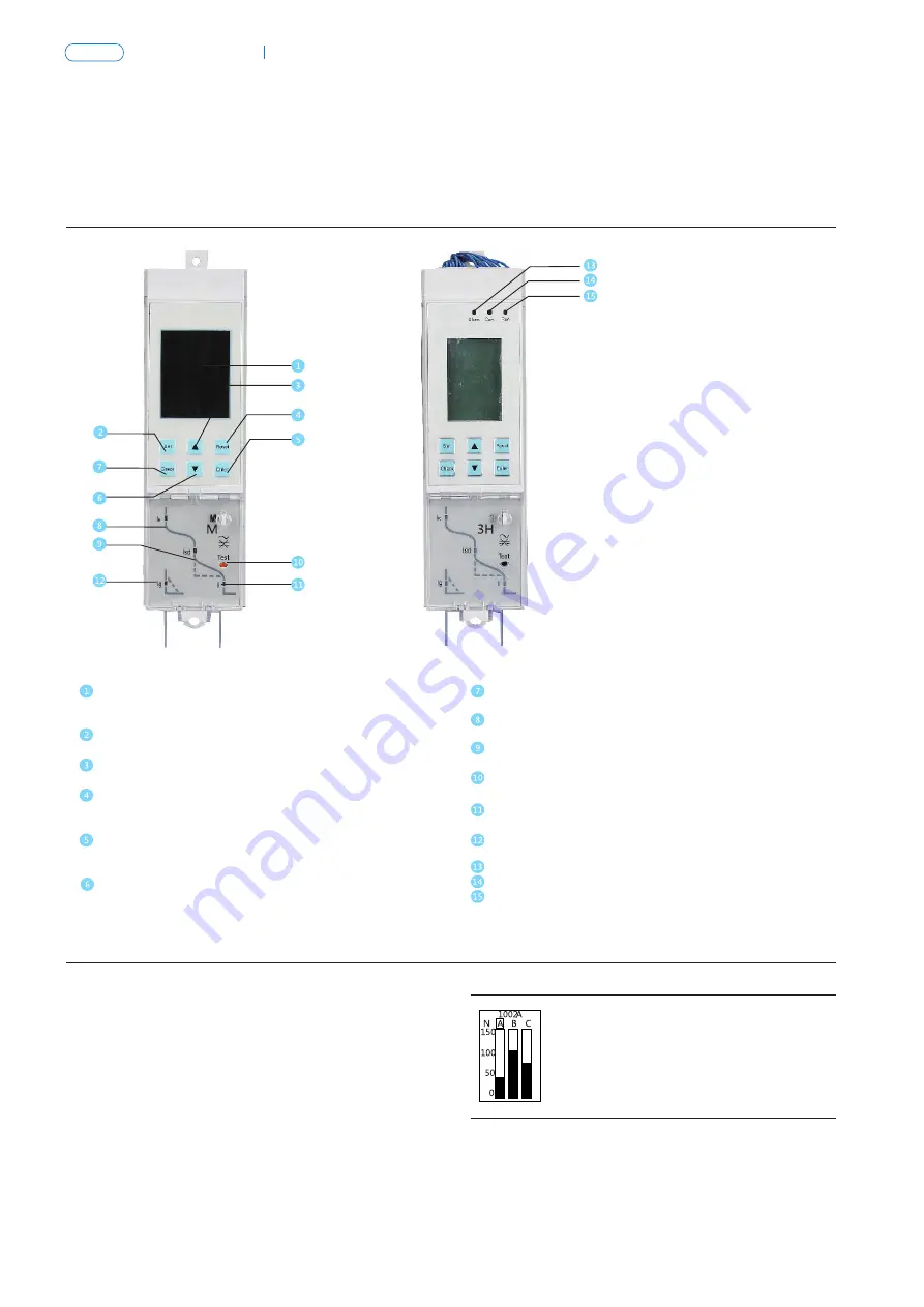
14.1 M/H and 3M/3H intelligent controller UI
M/H control
3M/3H control
Display window
Display current value, setting value, tripping time and
so on
“Set”
Switch to setting menu
“Up”
Change the marquee or the selected parameter
“Return”
Escape from this grade and return to upper menu or
cancel the current selected parameter
“Enter”
Enter into the next menu directed by the current item,
or select current parameter and store modifications
“Down”
Change the marquee or the selected parameter
“Check”
Switch to query menu
“IR” light
Overload long delay fault indication
“Isd” light
Short-circuit Short delay indication
“Test”
Trip test button
“Ii” light
Instantaneous Short-circuit fault indication
“Ig” light
Asymmetric earthing or neutral line fault indication
Alarm light
Communication light
Run light
Note: Method of 3M/3H controller application please refer to 3M/3H controller instruction.
3M/3H controller default interface and menu structure
3M/3H controller has four subjects menus and a default
interface:
The subjects menus are composed of 4 parts: measurement
menu, parameter set menu, protection parameter set menu,
history and maintenance menu.
14.2
3M/3H controller default interface
C
NA1
Air Circuit Breaker
P-080
P-079
NA1
Air Circuit Breaker
14.3 Explanation of M/H controller symbols
14.3.1 Explanation of symbols for reference
No.
1
2
3
4
5
6
7
8
9
10
11
12
13
14
15
16
17
18
19
20
21
22
23
24
symbol
IR= tR=
Isd= tsd=
Ig= tg=
Ii=
N=
TM
TRIP
RUN
SET
LIN
P┠ 0
ГES
RLR
SYS
DBS
DOS
FRU
COU
HDГ
DOC
H
F--
R--
Lg L1 L2 L3 LN
25
explanation
Long delay current setting, long delay time setting
Short delay current setting, short delay time setting
Earthing current setting, earthing time setting
Instantaneous current setting
Neutral line protection parameter setting
Trip simulated by software
Tripped
Run normally
Normally on: in settable state; Flickering: modifiable parameter
Storing state
Protection setting interface
Trip simulated by software setting interface
Alarm setting or query interface
System setting interface (current calibration , frequency setting …)
Communication setting interface of H-type controller
DO setting interface (H type with DO function )
Fault record query interface
Operation times and life query interface
Thermal capacity query interface
DO state query interface
Thermal capacity data
Fault record number
Alarm record number
Earthing ,A,B,C,N phase
The corresponding LED lamp will flash to indicate the fault type after tripping.
The LED lamps are always on when the system is normal.
14.3.2 Operation and display instruction
There are four states, default state, setting state, query state and tripping state.
① Default state: default state is also called measuring state. All fault indicating lamps are off and maximum phase current is displayed.
In this state, if “▲” or “▼” button is pressed, L1,L2,L3(LN),Lg current can be displayed in turn.
Example is shown below:
L1 phase current display interface
Summary of Contents for NA1
Page 1: ...Air Circuit Breaker Leading every step reliable new height ...
Page 2: ...Air Circuit Breaker Leading every step reliable new height ...
Page 3: ......
Page 4: ...Page P 001 Page P 039 ACB Air Circuit Breaker NA8G NA1 ...
Page 45: ...P 041 NA1 Air Circuit Breaker 1 3 4 5 7 8 11 12 13 14 15 ...


