NR8-200
、
NR8-630 Electronic Overload Relay
04
3.2
Operation and commissioning
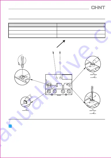
Figure 4 Installation and commissioning diagram
100
120
140
160
180
200
Stop
NO
Test
Reset
NO
100
120
140
160
180
200
95
96 97
98
NC
NO
Stop
Test
Reset
Test functiom
96
98
95
97
Test
Reset
97
95
98
96
96
95
Manual reset
function
Continuously
adjustable current
range
Emergency stop function
G
reen light Red light
Indicator status
Circuit working status
Normal
Overload delay
Phase-failure delay
Green light flashing, red light off
Green light flashing, red light on
Green light on, red light flashing
4
Maintenance
Clean the dust on the electronic overload relay timely. Conduct product test and maintenance every
half a year to ensure the smooth operation of the product and the good contact of NO and NC contacts.
Tighten the terminal screws with specified torque and align the load protection capability of the electronic
overload relay according to commissioning requirements.
Please be careful when handling and installing the relay. It is prohibited to move the product by crane
so that the product will not be damaged and its protection characteristics will not be changed due to
strong impact.
Table 4 Indicator status


