background image

02

NWC1 Series Self-healing Low Voltage Shunt Capacitors

and


heat


dissipation


of


the


capacitors


under


high


temperature


environment


and


keep


the


capacitors


away


from


heat


source

.

3

.

4


Transportation


conditions

The


capacitors


should


be


transported


within


original


package

 (

packed


in


foam


box

). 

The


product


should


be


handled


carefully


during


transportation

to


prevent


the


capacitor


body


from


deformation


due


to


collision

The


product


should


be


placed


on


upper


level


when


loaded


onto


the


truck

The


capacitor


assembly


must


be


placed


vertically


during


transportation

with


an


inclination


less


than


30


degrees

.   

4


Key


Technical


Parameters


and


Performance


4

.

1


See


Table


2


for


key


technical


parameters


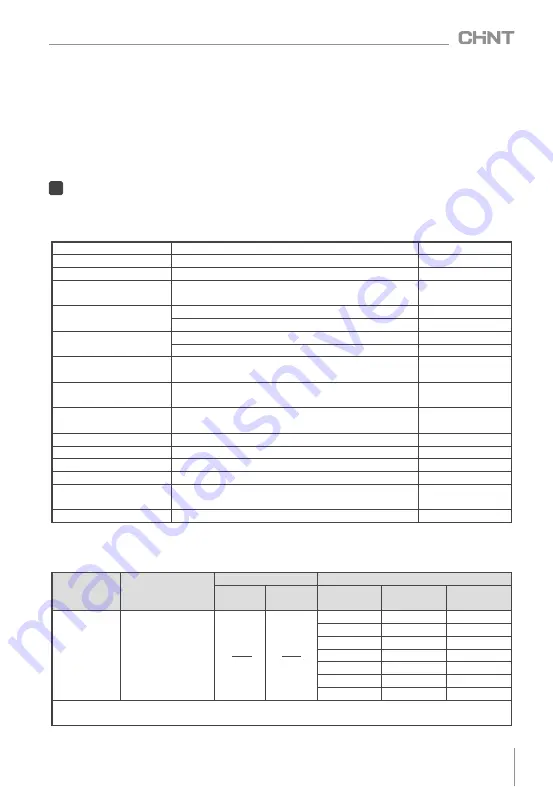
Table


2


Key


technical


parameters

Rate


voltage

 (

kV

)

0

.

4

0

.

69


See


Table


3

Rate


capacity

 (

kvar

)

5

~

100


See


Table


3

Rate


frequency

 (

Hz

)

50


or


60


Default


50

Capacitance


deviation

 (%)

-

5

~+

8


Short


circuit


discharge


before


test


Dissipation


factor

≤ 

30kvar


product

tan

δ≤

0

.

0012

30kvar


product

tan

δ≤

0

.

0015

Withstand


voltage

 (

kV

)

Inter

-

pole

power


frequency


2

.

15U

N

2s

Pole

-

to

-

case

2

.

0


U

N

+

2


kV


or


3


kV

 (

take


higher

), 

5s

Maximum


allowable


overvoltage

1

.

1U

N

,


no


more


than


8h


of


continuous


operation


within


24h

Maximum


allowable


overcurrent

1

.

3I

N

no


more


than


2h


of


continuous


operation


within


24h


Short


time

2

.

0IN

Self

-

discharge


characteristics

Residual


voltage


drops


from

 √

2U

N


to


75V

(

DC

or


below


within


3min


after


power


off

.

Ambient


temperature

 (℃)

-

25

~+

50

 (-

25

/

C

)

Customizable

40

~+

50

Relative


temperature

50

at


40

℃, ≤

90

at


20

Altitude

 (

m

)

2000

Tightening


torque

 (

N

?

m

)

M6


screw

 ≤

7

M8


screw

 ≤

10

Safety


protection

Self

-

healing

 + 

overpressure


protection

discharge


device

Short


circuit


discharge


before


test

Installation


method

Vertical

        Note

Other


voltages


are


customizable

the


maximum


capacity


is


100kvar

.

4

.

2


See


Table


3


for


specifications


and


outline


dimensions


of


main


models

Table


3


Specifications


and


outline


dimensions


of


main


models


Qc

√ 

3U

N


Qc


U

N

Rated


current


I

N

(

A

)

3

-

three


phase

1

-

single


phase

Rated


voltage 

U

N

(

kV

)

Optimal


capacity


Qc

(

kvar

)

Outline


and


installation


dimensions

Capacity


range

Height


H

Figure


number

0

.

4

0

.

415

0

.

45

0

.

525

0

.

69

5

7

.

5

8

10

15

16

18

20

25

30

40

50

60

,


80

100

1

~

10

160

Figure


1

12

~

16

220

Figure


1

18

~

20

260

Figure


1

22

~

30

230

Figure


2

32

~

40

270

Figure


2

45

~

60

300

Figure


3

80

~

100

300

Figure


4

Note

See


the


outline


and


installation


dimensions


in


this


manual


for


the


figure


number


of


outline


and


installation


dimension


drawings

Summary of Contents for NWC1 Series

Page 1: ...Standard IEC 60831 1 2014 IEC 60831 2 2014 NO 2021 01 NWC1 Series Self healing Low Voltage Shunt Capacitors ...

Page 2: ...maintenance 2 Installation in any damp condensed phase environment with inflammable and explosive gas is forbidden 3 When the product is being installed or maintained the power must be switched off 4 You are prohibited from touching the conductive part when the product is operating ...

Page 3: ...ation Commissioning and Operation Main Features Outline and Installation Dimensions Analysis and Troubleshooting of Faults Maintenance and Storage Product Selection and Ordering Information 11 Environmental Protection 01 01 01 02 04 04 06 06 07 08 08 Use Purpose and Application Range Warranty Period Environmental Protection and Law Regulations ...

Page 4: ...wer electronic equipment frequency converter energy saving transformation such as motor speed regulation variable frequency air conditioner etc DC rectifier inverter electrolytic plating equipment electric arc furnace and intermediate frequency furnace etc See Table 1 for capacitor selection and harmonic suppression measures under harmonic environment 3 Conditions for Normal Use Installation and T...

Page 5: ...overvoltage 1 1UN no more than 8h of continuous operation within 24h Maximum allowable overcurrent 1 3IN no more than 2h of continuous operation within 24h Short time 2 0IN Self discharge characteristics Residual voltage drops from 2UN to 75V DC or below within 3min after power off Ambient temperature 25 50 25 C Customizable 40 50 Relative temperature 50 at 40 90 at 20 Altitude m 2000 Tightening t...

Page 6: ... fuse for short circuit protection For capacitors with capacity 30kvar user can use miniature circuit breaker for short circuit protection For capacitors with capacity 30kvar miniature circuit breaker is not recommended RT36 or NT00 NWC1 series square case products consist of fully independent units with automatic protection functions The units use cylindrical stretched aluminum enclosure while th...

Page 7: ...ng lug See Table 6 for the selection of conductor sectional area Figure 5 Capacitor installation drawing Table 5 Installation spacing and safety distance Capacity kvar Minimum installation spacing S1 mm Safety distance at the top of capacitors S2 mm 1 20 30 50 22 32 50 50 35 100 80 50 6 4 Preparation and inspection before use 6 4 1 Before using the capacitor user should check if the model on the n...

Page 8: ...orage 7 1 Daily maintenance and calibration Check if the operating current of the capacitor is normal by using the amperemeter and compensation controller in the cabinet Check if there is any deformation oil leakage and overheating Abnormalities such as overcurrent and overtemperature caused by harmonic will reduce the service life of the capacitor and can cause damage to other components and cond...

Page 9: ...ms are typical when the grid harmonic is too big or there is intermittent resonance in the grid Conduct grid harmonic test or check if there are harmonic sources such as frequent converter rectifier intermediate frequency furnace or electric arc furnace installed at load end See 3 3 2 for harmonic suppression measures 5 Sometimes there is buzzing sound in the cabinet during operation There is harm...

Page 10: ...tment process or be sent to the recycling station for assortment dismantling and recycling according to local regulations In order to protect the environment the product or product parts should be disposed of according to the industrial waste treatment process or be sent to the recycling station for assortment dismantling and recycling according to local regulations 10 1 User should provide produc...

Page 11: ...08 NWC1 Series Self healing Low Voltage Shunt Capacitors DR J03 NWC1 Series Self healing Low Voltage Shunt Capacitors IEC 60831 1 2014 IEC 60831 2 2014 ...

Page 12: ...NWC1 Series Self healing Low Voltage Shunt Capacitors User Instructions ...

Reviews: