NXM 系列塑料外壳式断路器
0ZTD.463.1213.1.EN
共 11 页
第 9 页
标记 处数 更改文件号
签字
日期
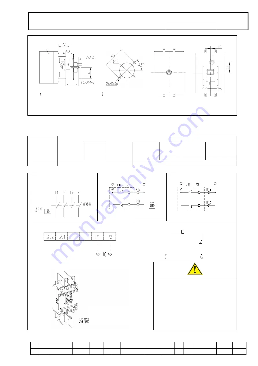
Installation size of manual operating mechanism
NXM-63, 125, 250 NXM-1250/1600
400, 630, 800, 1000
Table 5
Installation Size of NXM Series Manual Operating Mechanism
Unit: mm
Size code
Product model
NXM-63
NXM-125
NXM-160
NXM-250
NXM-400
NXM-630
NXM-800
NXM-1000
NXM-1250
NXM-1600
N
53.5
61.5
63.5
98
97
97
68.5
L
65
95
Wiring of special tripper for prepaid
electricity meter
Auxiliary contact wiring
Wiring of alarm contact
Wiring of under voltage tripper
Wiring of shunt tripper
Flash barrier
①
Be sure to install flash barriers
before product operation.
②
Check if the wiring is correct.
③
After installation, the insulation
resistance to the ground shall not be
less than 10m Ω.
Breaker
L Consult with the manufacturer for
purchase of other sizes
Diagram of handle
installation opening
Breaker
Tripper
Power
Closing circuit
Opening circuit
Power
supply
Power
Insert in the direction of the
arrow on the flash barrier


