05
NXMS series Moulded-Case Circuit-Breaker
P4
P9
K
M1
L2
L6
L6
4
×φ
d2
6
×φ
d2
Q
L7
L8
P6
P5
P7
P8
P6
P5
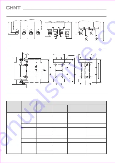
Installation diagram
Mounting plate hole size (3P)
Mounting plate hole size (4P)
L5
L4
K
L5
L4
P8
P6
Figure 8 NXMS-400/630/1000
plug-in structure
Figure 9 NXMS-160
plug-in structure
Figure 10 NXMS-250
plug-in structure
Figure 11 NXMS series plug-in wiring outline and installation size
Table 2 - NXMS series back-panel wiring outline and installation size
Unit: mm
Size type
Size code
Product type
NXMS-160
NXMS-250
NXMS-400
NXMS-630
NXMS-1000
Outline size
W
P1
P2
P3
P4
P5
P6
P7
P8
P9
M2
30
--
63.5
96.5
38
--
75
--
135
M8
35
--
67.5
108.5
47.5
77
95
132
150
M10
44
18
58
93
60
88
111
--
--
25
--
70
20
84
--
87
143.5
158.5
--
--
27
--
13


