background image


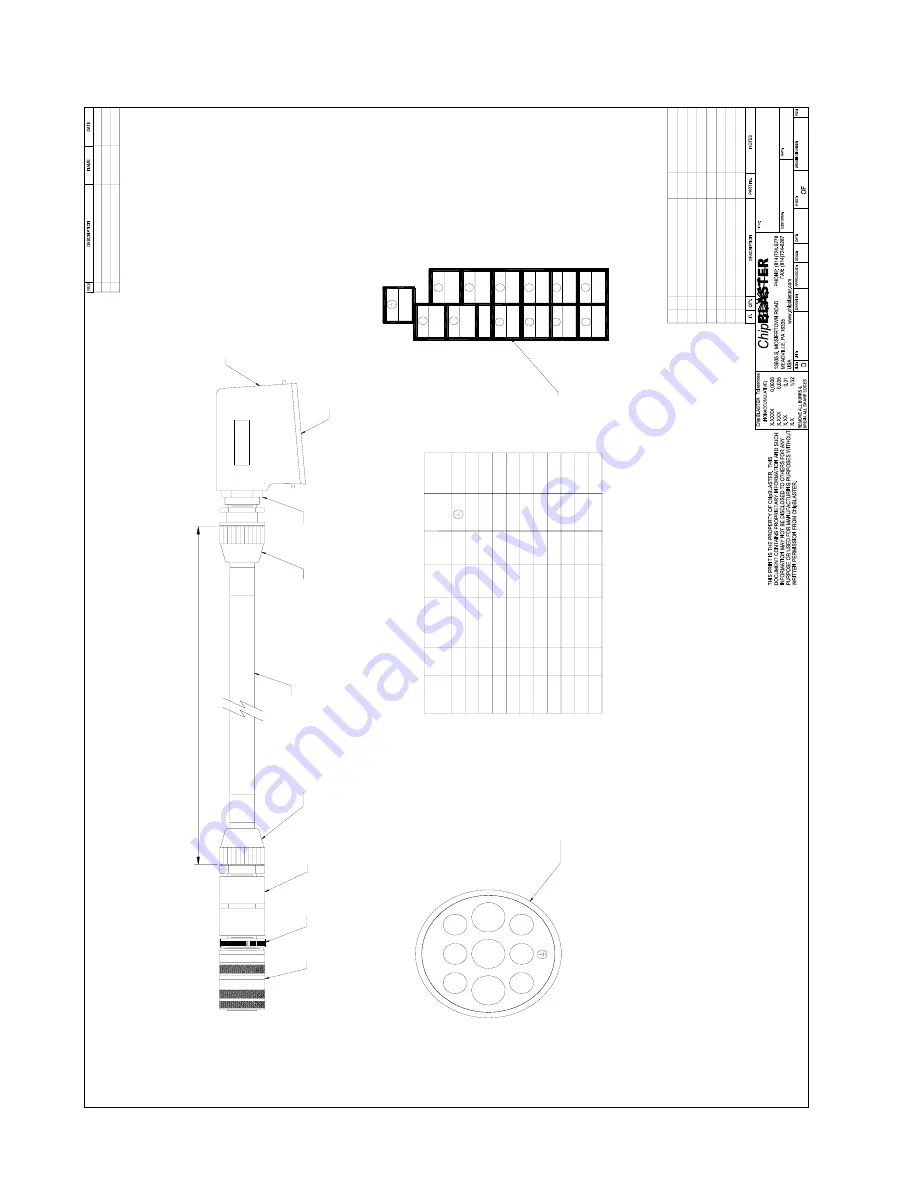
20.0. ELECTRICAL DRAWINGS (Cont.): 

10

2

3

1

PI

N #

A

D

PI

N #

F

E

16

'

16

'

16

'

16

'

8G

16

'

6I

16

'

--

-

--

-

--

-

12

B

16

'

HARTIN

G

CIRCUL

A

R

LENG

T

H

L1

PE

L2

L3

YELL

O

W

YEL

LO

W

BL

AC

K

BL

AC

K

-

-

-

COM3

COM1

-

-

-

H

16

'

4

7

8

8

1

C

O

N

N

E

C

T

OR

, C

IR

C

U

LA

R

 9 C

O

N

T

5161

-

509

2

509

2

509

2

509

2

740

6

740

6

740

6

PART N

O

-

-

50

95

PE

9

B

A

DDE

D D

V

30

JR

G

23

MAY

07

YEL

LO

W

YEL

LO

W

COM

3

COM

1

COM

1

COM

3

E2

R

E

V

ISE

D E2

 T

O

 PI

N B


C

25

 J

U

N

 0

7

RB

WA

S E1

 FRO

M

 PI

N

 1

1

D

30-

80

-1

D

OOSA

N

D

A

EWOO L

A

T

H

E

D1

6 D3

0 DV

30

 IN

T

E

R

F

A

C

E

 C

A

B

LE

JR

G

JR

G

30

JU

N0

6

30

52

0-

1

11

AS

 N

O

T

E

D

C

1:

16

15

'

1T

1

/L3

1R1/

L1

NO

T

E

#1

1S

1

/L2

3

1

9

4

2

PE

11

IN

S

E

R

T

, 12 P

IN

 FE

M

A

LE

5810

1

2

HO

OD

, SI

DE

 E

N

T

R

Y

2

1

5807

3

4

5

6

7

3

4

CON

N

ECT

O

R, 3/4"

 C

O

N

DUI

T


2

5506

CON

DUIT

, 3

/4"

 NON

-M

E

T

A

LLC

15'

5590

5

6

1

F

TG

, C

O

UP

LI

N

G

 3/

4

" N

P

GR

A

Y

 P

V

C

5160

1

C

IR

C

U

LA

R

 M

IL

L

 T

O

 NP

T

 A

D

APT

ER

5164

2)

 M

A

LE

 CONN

EC

TOR,

 VI

EWE

D

 FROM T

E

RMI

N

ATI

O

S

IDE

1)

 F

E

M

A

LE

 CONN

EC

TOR,

 V

IEW

ED FORM TER

M

IN

A

T

IO

N S

IDE

NO

T

E

10

6

5

5484

ADAPT

E

R

, P

G

21

x3

/4

NPT

2

8

7

9

12

11

A

B

C

D

E

F

G

H

I

L3

L2

L1

E2

NOTE#

2

20

20

20

20

9

BL

AC

K

COLO

R

GRN W

/Y

LW

10

10

20

20

20

CRT.N

O.

E2

9

AW

G

10


Summary of Contents for STANDARD UNIT D30-80-1

Page 1: ...SYSTEM STANDARD AND CERTIFIED STATEMENT NUMBER 00 10 005 INSTALLATION OPERATION and SERVICE MANUAL ChipBLASTER Inc 13605 South Mosiertown Road Meadville PA 16335 USA www chipblaster com Telephone 814 724 6278 Fax 814 724 6287 For your records please list serial number from nameplate ______________ REV K ...

Page 2: ...BLES C 31 MAR 2006 WPA DWG REV SECT 21 0 D 5 APR 06 R B DWG REV PAGE 42 E 19 MAY 2006 R B ADDED PAGE 25 CHECKING OIL USING SIGHT GAUGE F 10 JULY 2006 RRW ADDED DAEWOO INTERFACE G 8 JAN 2007 R B REVISED SHIP LOOSE ITEMS PAGE 59 H 18JUN07 JRG ADDED KIWA CABLE J 21JUN07 JRG ADDED LOW PRESSURE OPTION K 11JAN08 TD ADDED AIR PURGE PROCEDURE ...

Page 3: ...L This manual covers the following ChipBLASTER model D30 80 1 STANDARD UNIT 60Hz For the model number of your unit refer to the data nameplate located on the enclosure door DATA NAME PLATE UNIT MODEL NUMBER UNIT SERIAL NUMBER ...

Page 4: ...This manual covers the following ChipBLASTER model D30 80 1 CE CERTIFIED UNIT 50Hz For the model number of your unit refer to the data nameplate located on the enclosure door DATA NAME PLATE UNIT MODEL NUMBER UNIT SERIAL NUMBER ...

Page 5: ...alled and connected to electric service per the installation portion of this manual All persons who will be operating and maintaining this machine must read and understand this manual DO NOT AT ANY TIME USE FLAMMABLE OR EXPLOSIVE FLUIDS IN OR NEAR MACHINE DO NOT STAND ON MOTORS SUPPORTS or JUNCTION BOXES WHILE WORKING ON THE ChipBLASTER REFER TO SECTION 4 1 FOR EXPLANATION OF MARKINGS 1 0 ...

Page 6: ...arms Section 13 0 Page 22 Preventive maintenance Section 14 0 Page 22 Schedule Figure 2 Section 14 1 Page 23 High pressure pump Check oil Dipstick Section 14 2 Page 24 High pressure pump Check oil Sight gauge Section 14 2 Page 25 High pressure pump Oil change procedure Section 14 3 Page 26 High pressure pump Check belt Section 14 4 Page 29 High pressure pump Check for leaks Section 14 5 Page 29 Hi...

Page 7: ...echanical assembly Section 22 0 Page 60 Gauge Panel Top Section 22 1 Page 60 Control Panel Front Section 22 2 Page 61 Control Panel Inside Enclosure Section 22 3 Page 62 Sub Plate Elevation Left Side Section 22 4 Page 63 Sub Plate Elevation Right Side Section 22 5 Page 64 Manifold block assembly Section 22 6 Page 65 Filter Assembly Section 22 7 Page 66 Ship Loose Items Section 22 8 Page 67 Spare P...

Page 8: ...re believed to be accurate and may contain ChipBLASTER Inc proprietary information which is privileged confidential or subject to copyright patent belonging to ChipBLASTER Inc This manual is intended for the operation and maintenance of your ChipBLASTER unit You are hereby notified that any dissemination distribution copying or action taken in regard to the content of this manual is strictly prohi...

Page 9: ...iven 4 1 EXPLANATION of MARKINGS Symbols Meaning of Symbols DANGER Indicates that error in operation may lead to death or serious injury WARNING Indicates that error in operation may lead to injury 1 to people or that these errors may cause damage to physical property 2 1 Such things as injury burns or shock that will require hospitalization or long periods of outpatient treatment 2 Physical prope...

Page 10: ...en closing lids or covers Oil skimmer cover CUTTING HAZARD Any point where exposed fan blades may cause a cutting hazard to fingers when guard or inlet hose is not in place Do not operate without guard or inlet hose in place Inlet to MistBLASTER PINCH POINT Any point where fingers may be pinched by the motion of a belt Do not operate with guard or cover open Oil skimmer LIFTING HAZARD Use caution ...

Page 11: ...WER Lock out and tag any and all disconnect switches before performing any maintenance work on equipment SAFETY GLASSES REQUIRED When removing filter bags or working on equipment safety glasses must be worn to prevent injury from splashing fluid or from other hazards MACHINE STARTS AUTOMATICALLY ChipBLASTER equipment will start without operator input Do not remove any guards or covers until discon...

Page 12: ...ll not result SAFE OPERATING PRESSURE Safe operating pressure will be listed below symbol in PSIG and Bar Do not operate above stated pressures as equipment damage or personal injury will result DO NOT STEP OR STAND ON Do not use surface as a step or platform when servicing equipment Motors and electrical boxes are not designed to be used as steps or platforms and injury may result from falls READ...

Page 13: ...s hazards to personnel will be present and injury to personnel could result LIFTING POINT Machine must only be lifted at points indicated in order to avoid mechanical damage and personal injury Lifting slings or chain slings must be adequately sized to carry the weight of the MistBLASTER Refer to MistBLASTER footprint drawing for actual weight BURN HAZARD HOT SURFACE Surface of transformer will be...

Page 14: ...des adjacent to the electrical enclosure Forks must extend the full distance under ChipBLASTER The fork truck lifting capacity must be sufficent to safely lift the ChipBLASTER without tiping Refer to footprint drawing Section 23 for machine dry weight MOVE SLOWLY AS NOT TO DROP THE ChipBLASTER DO NOT TRY TO MOVE ChipBLASTER WITH FLUID IN FILTERS DO NOT STAND UNDER ChipBLASTER AT ANY TIME If MistBL...

Page 15: ...emove the lumber that is used to hold the unit in place during transporation using a phillips screw driver or an electric screw gun 7 2 2 Before you remove the ChipBLASTER from the skid take a moment to locate the bags containing the casters 7 2 3 When removing the ChipBLASTER from the skid lift unit from the sides only Insure the forks extend completely under the ChipBLASTER unit DO NOT AT ANY TI...

Page 16: ...t one end to ChipBLASTER outlet located beneath the electrical enclosure Connect other hose end to the machining center spindle turret or other designated tool orifice 8 1 2 Locate the 25mm 1 clear hose and clamps that ChipBLASTER Inc has provided This is the return line Connect one end of the hose to the inlet hose barb on the ChipBLASTER return pump located beneath the electrical enclosure Conne...

Page 17: ...IF CONNECTING TO LOAD SIDE IF CONNECTING TO A MAIN DROP SIZE DISCONNECT AND WIRE BASED ON INFORMATION SUPPLIED ON THE ChipBLASTER NAMEPLATE 9 1 POWER INTERFACE REFER TO SECTION 20 0 DRAWING D30 003 9 1 1 Connect 3 phase power to the line side of 1 CB or to pins 1 2 3 if power will be supplied via the 12 pin power control interface plug 9 1 2 Connect the ground wire to a ground terminal located in ...

Page 18: ...ressure to build and open the contact 9 2 4 Wire the ES Error Signal relay to terminals E E1 or E E2 contacts into the emergency stop or feed hold circuit of the machining turning center Or if using the 12 pin power control interface plug wire to pins 10 11 or 10 12 ES is the ChipBLASTER error signal NOTE Machine tool damage could result if the ES signal is not properly interfaced NOTE THE ES RELA...

Page 19: ...ALVES ARE OPEN AND THAT PUMPED COOLANT CAN FLOW FREELY TO THE INLET OF THE HIGH PRESSURE PUMP 11 0 SYSTEM AIR PURGE 11 1 SINGLE AND DUAL FILTER 11 1 1 Loosen the thumb screw on each automatic vent valve two turns so that trapped air can escape both filters 11 1 2 Press the AIR PURGE push button to remove the air from the filters Continue to hold the button until you no longer hear air escaping fro...

Page 20: ...H PRESSURE High pressure coolant leaving the pump goes to the manifold block which contains a regulator and solenoid valve The regulator is adjustable to relieve coolant at the system operating pressure The regulator protects the high pressure coolant system from over pressure condition Relieved coolant is returned to the inlet of the return pump Upon activation of coolant on relay CR1 the normall...

Page 21: ...ChipBLASTER Inc 21 12 0 OPERATION Cont 12 3 COOLANT FLOW DIAGRAM Figure 1 Figure 1 12 3 ...

Page 22: ...et a fault 13 2 1 Determine the cause of the fault and correct Reset motor overload s and or correct dirty filter switch selector valve to clean filter or replace dirty filter cartridge Note power to unit must be cycled off on to reset the ES relay circuit Re energize the required M code to start the ChipBLASTER 14 0 PREVENTATIVE MAINTENANCE DO NOT ATTEMPT ANY SERVICE ON ChipBLASTER UNIT WITH POWE...

Page 23: ...ChipBLASTER Inc 23 14 0 PREVENTATIVE MAINTENANCE Cont 14 1 PREVENTATIVE MAINTENANCE SCHEDULE Figure 2 14 1 Figure 2 ...

Page 24: ...oil fill cap located on top of the pump 14 2 2 The oil level must be maintained between the full and add marks If required add oil refer to Section 14 3 6 Oil Fill Cap Dipstick DO NOT ATTEMPT ANY SERVICE ON ChipBLASTER UNIT WITH POWER ENERGIZED REMOVE ALL ENERGY SOURCES AND LOCK OUT TAG OUT OIL FILL CAP DIPSTICK FAILURE TO USE MOBIL 1 FULLY SYNTHETIC 15W 50 WILL VOID YOUR WARRANTY ADD Mark FULL Ma...

Page 25: ...ight glass when the pump is stopped 14 3 2 The oil level must be maintained between the full and add marks If required add oil refer to Section 14 3 6 DO NOT ATTEMPT ANY SERVICE ON ChipBLASTER UNIT WITH POWER ENERGIZED REMOVE ALL ENERGY SOURCES AND LOCK OUT TAG OUT OIL LEVEL FULL MARK OIL LEVEL LOW MARK FAILURE TO USE MOBIL 1 FULLY SYNTHETIC 15W 50 WILL VOID YOUR WARRANTY 14 2 ...

Page 26: ...obil 1 fully synthetic 15W 50 oil 14 3 2 Remove accesses panel from right side as viewed from enclosure end use 4mm hex head wrench 14 3 3 Locate and remove the oil fill cap dipstick located on top of pump 14 3 4 Locate and remove the drain plug use 17mm wrench located on back side of pump opposite the head end Allow oil to drain into a container capable of holding at least 1 liter 32 ounces FAILU...

Page 27: ...oil is drained from pump reinstall the plug in back of pump Torque to 20 Nm 180 In LB PROPERLY DISPOSE OF OIL PER LOCAL REGULATIONS DO NOT REUSE OIL 14 3 6 Locate High Pressure Pump fill opening ON TOP OF PUMP Place a funnel with flexible spout into opening FUNNEL W FLEX SPOUT 14 3 OIL FILL OPENING ...

Page 28: ...r 3 to 4 minutes 14 3 9 Check level and if required add small amounts slowly until level is at FULL indicator 14 3 10 Reinstall dipstick plug Do not over tighten 14 3 11 Reinstall right side panel Tighten BHCS to 12 Nm 106 In Lb DO NOT RUN HIGH PRESSURE PUMP WITHOUT OIL AS DAMAGE WILL RESULT AND VOID YOUR WARRANTY DO NOT ATTEMPT ANY SERVICE ON ChipBLASTER UNIT WITH POWER ENERGIZED REMOVE ALL ENERG...

Page 29: ...ace side panel before operating the ChipBLASTER unit 14 6 HIGH PRESURE PUMP REBUILD 14 6 1 Due to the manufacturing tolerances required for the internal parts of the high pressure pump rebuilding the high pressure it is NOT recommended A new or re built replacement pump can be purchased from ChipBLASTER When ordering a replacement pump from the ChipBLASTER service department advise the contact per...

Page 30: ...rench 14 14 3 Remove lid and inspect for damage Be careful not to damage filter hold down plate seal or spring Set lid aside 14 14 4 Pull the filter cartridge out of the housing 14 14 5 Install the new filter cartridge in the housing Ensure cartridge it is all the way down and firmly seated 14 14 6 Inspect the lid seal O ring for cracks or tears replace if damaged 14 14 7 Inspect filter hold down ...

Page 31: ...B 14 15 3 Ensure that pressure is relieved from the housing Then remove the filter lid hold down screws using a 17mm wrench 14 15 4 Remove lid and inspect for damage Be careful not to damage filter hold down plate seal or spring Set lid aside 14 15 5 Pull the filter cartridge out of the housing 14 15 6 Install the new filter cartridge in the housing Ensure cartridge it is all the way down and firm...

Page 32: ...ChipBLASTER Inc 32 14 0 PREVENTATIVE MAINTENANCE Cont 14 16 FILTER REPLACEMENT FORM PLEASE MAKE A COPY OF THE FILTER REPLACEMENT FORM BEFORE ORDERING 14 16 ...

Page 33: ... 29 3 The ChipBLASTER must be powered down and the disconnect placed in the OFF position and locked out 14 29 4 Remove the inlet and outlet hoses by loosening the hose clamps Inspect the inlet and outlet for chips that may have accumulated Remove chips as required 14 29 5 Remove the four 4 bolts using a 7 16 wrench that hold the casting in place 14 29 6 Clean all chips from the casting and impelle...

Page 34: ...ticking Replace solenoid valve pressure is operating Solenoid coil is faulty Replace coil Regulator sticking Replace regulator Coolant is pulsating from high High pressure pump valve pressure nozzle is sticking Clean or replace the valve Hose plugged Replace Hose Return pump not operating MR3 trip or not turned on Reset or turn on MR3 Circuit Breaker 2CB trip Reset Circuit breaker 2CB Return pump ...

Page 35: ...ORMAL HIGHER NOZZLE PLUGGED WITH CHIPS NOZZLE TOO SMALL YES YES NO DO YOU HAVE CORRECT PRESSURE AT THE MACHINE TOOL NO DEFECTIVE STARTER OR OVERLOAD FAULTY MOTOR IS POWER ON FAULTY REGULATOR N O SOLENOID NOT WORKING BROKEN BELT NO 15 0 TROUBLESHOOTING Cont NOTE BEFORE RESETTING A MOTOR STARTER OVERLOAD FIRST DETERMINE THE CAUSE AND CORRECT FOR ADDITIONAL INFORMATION PLEASE CONTACT ChipBLASTER SERV...

Page 36: ...trical enclosure The regulator will need to be accessible during this procedure for achieving settings over 69 Bar 1000 psi 16 0 2 Regulator adjustment The regulator is used to regulate the pressure to the machining center from over pressure 16 0 3 Loosen locking nut using a wrench 16 0 4 Turning the adjustment screw in using a 3 16 hex head wrench clockwise increases the regulator setting 16 0 4 ...

Page 37: ...easily removed DO NOT PRY OR FORCE THE DRIVE BELT OFF OF THE PULLEYS THIS MAY RESULT IN PERMANENT DAMAGE TO THE PULLEY OR BELT ONCE THE DRIVE BELT HAS BEEN REMOVED VISUALLY INSPECT IT FOR ABNORMAL WEAR AND TOOTH SHEAR REPLACE THE BELT AS NECESSARY 17 3 THE REPLACEMENT PUMP 17 3 1 Transfer the driven pulley intake discharge fittings and the high pressure pump brackets with fasteners from the defect...

Page 38: ...points when the drive is properly aligned After aligning the sprockets check the rigidity of the supporting framework Shafts should be well supported to prevent distortion and a resulting change in the center distance under load Do not use spring loaded or weighted idlers Idler sprockets or pulleys must be locked into position after adjusting belt tension Please note At least one sprocket must hav...

Page 39: ... deflection height required for the drive The deflection height is always 1 64 per inch of span length For example a 32 span length requires a deflection of 32 64 or 1 2 To measure the deflection height place a straightedge from sprocket to sprocket on top of the belt or wrap a string or steel tape around the sprockets on top of the belt This will serve as a reference line to measure deflection in...

Page 40: ...er DHP Belt Horsepower or Motor Horsepower x Recommended Service Factor BHP Brake Horsepower Or Motor Horsepower RPM Speed of Fastest Shaft Pitch Diameter Diameter of Smallest Sprocket REFER TO CHART FOR DEFLECTION AND FORCE FOR THE MODEL IN USE REINSTALL ALL GUARDS PROTECTIVE PANELING ON THE ChipBLASTER UNIT 18 5 Deflection and force chart 18 5 ...

Page 41: ... IF THERE IS PRESSURE PRESENT DO NOT OPEN FILTER HOUSING SEEK ASSISTANCE FROM QUALIFIED MAINTENANCE PERSONNEL TO RELIEVE PRESSURE 19 3 Install Purge Hose 19 3 1 Remove right side access panel from ChipBLASTER unit using 4mm hex head wrench Panel on right side as viewed from enclosure end 19 3 2 Locate remove NPT plug from end of manifold block using 3 8 hex head wrench 19 3 3 Install NPT to hose a...

Page 42: ... 19 4 1 Manually energize CR1 three 3 times for three 3 seconds 19 5 REPLACE ALL PLUMBING FITTINGS AND PANELS TO THEIR ORIGINAL CONFIGURATION REPLACE ALL GUARDS BEFORE OPERATING ChipBLASTER Any questions on the Contamination Purging Procedures please contact the ChipBLASTER Service Department at 814 724 6278 Have the model and serial number of your ChipBLASTER unit 19 0 ...

Page 43: ...pBLASTER Tolerances 0 0005 0 01 0 005 1 32 BREAK ALL SHARP EDGES NONACCUMULATIVE X XX REMOVE ALL BURRS X X BLASTER X XXXX X XXX Chip UNIT SIZE C QTY CUSTOMER APPROVED BY FAX 814 724 6287 PHONE 814 724 6278 BLASTER www chipblaster com DRAWN BY DATE TITLE IT DRAWING NUMBER OF SHEET REV MAT L PART No REV DESCRIPTION DATE SCALE NOTES DESCRIPTION 13605 S MOSIERTOWN ROAD MEADVILLE PA 16335 USA NAME POWE...

Page 44: ...ER OF SHEET REV MAT L PART No REV DESCRIPTION DATE SCALE NOTES DESCRIPTION 13605 S MOSIERTOWN ROAD MEADVILLE PA 16335 USA NAME POWER WIRING D16 D30 CE APPROVED R B 16 MAY 06 D 001 CE 1A 3 A NTS 129 126 127 128 125 124 2L3 2L1 1 CB D16 CHART MODEL D30 16 A 16 A 380 VAC 3 Ø 50 HZ 2 CB 16 A 16 A 2L1 2L3 2L2 1L3 123 122 121 120 117 118 119 116 115 110 114 113 112 111 109 108 107 106 SEE CHART L1 L2 PE...

Page 45: ... PART No REV DESCRIPTION DATE SCALE NOTES DESCRIPTION 13605 S MOSIERTOWN ROAD MEADVILLE PA 16335 USA NAME CONTROL WIRING D30 80 1 JRG JRG 21JUN07 D30L 002 2 3 A NTS 219 107 DIRTY FILTER DETECT SET 15PSI 227 228 100 223 224 225 226 220 221 222 5 9 100A TM1 COM DIRTY FILTER ALARM PS1 108 AL1 100A 216 217 218 212 213 214 215 CR31 100A 100A PB1 24 21 11 100A 14 13 MR1 14 208 209 210 211 205 206 207 14...

Page 46: ...o REV DESCRIPTION DATE SCALE NOTES DESCRIPTION 13605 S MOSIERTOWN ROAD MEADVILLE PA 16335 USA NAME CONTROL WIRING D30 80 1 JRG JRG 11JAN06 D30 002 2 3 E NTS 228 227 226 225 224 223 222 221 220 219 218 217 216 215 214 213 212 211 210 209 208 207 206 205 204 203 202 201 200 100 129 MR1 A1 A2 COM 127 ES CR3 G A1 MR3 A2 MR1 OL A2 A1 ES 1 2 DUMP SOLENOID BLACK WHITE READY SIGNAL ON OKAY 95 96 100 TM1 9...

Page 47: ...0 0005 0 01 0 005 1 32 BREAK ALL SHARP EDGES NONACCUMULATIVE X XX REMOVE ALL BURRS X X BLASTER X XXXX X XXX Chip UNIT SIZE C QTY CUSTOMER APPROVED BY FAX 814 724 6287 PHONE 814 724 6278 BLASTER www chipblaster com DRAWN BY DATE TITLE IT DRAWING NUMBER OF SHEET REV MAT L PART No REV DESCRIPTION DATE SCALE NOTES DESCRIPTION 13605 S MOSIERTOWN ROAD MEADVILLE PA 16335 USA NAME AND POWER INTERFACE D30 ...

Page 48: ...RD CONTROL JRG JRG 11JAN06 D30 003 3 3 D NTS 1DS 3 2 1 GND PE L3 L2 L1 ChipBLASTER STANDARD POWER INTERFACE PLUG 12 PIN MACHINING CENTER 5 6 7 9 8 11 12 10 ES ES CR1 ERROR SIGNAL READY SIGNAL COMMON N O ERROR SIGNAL READY SIGNAL CLOSED OKAY N C ERROR SIGNAL READY SIGNAL OPEN OKAY 3 PHASE SUPPLY INPUT REFER TO POWER WIRING FOR CURRENT DRAW COOLANT 1 ON COMMON INDEX COMMON FILTER DIRTY SIGNAL SET 15...

Page 49: ...TURING PURPOSES WITHOUT WRITTEN PERMISSION FROM ChipBLASTER UNIT SIZE B CUSTOMER APPROVED BY FAX 814 724 6287 PHONE 814 724 6278 BLASTER www chipblaster com DRAWN BY DATE TITLE DRAWING NUMBER OF SHEET REV MAT L REV DESCRIPTION DATE SCALE 13605 S MOSIERTOWN ROAD MEADVILLE PA 16335 USA NAME D16 D30 CONTROL INTERFACE CABLE ASS Y D16 AND 30 12 PIN 6M POWER AND JRG JRG 20NOV06 9513 6 1 1 AS NOTED A NTS...

Page 50: ...AWG 15 CONDUCTOR CB PART No 5140 9 8 7 6 5 4 3 2 1 MARK BOTH ENDS OF WIRES WITH WIRE MARKERS ITEM 6 1 1 1 2 3 4 6 5 BOOT HEAT SHRINK SIZE 13 PLUG FREE HANGING 9 PIN SIZE 13 9 18 SOCKET CRIMP 24 20 AWG WIRE MARKERS TYTON TAG 26L 105 5141 5148 5147 5151 4098 E 6 E2 8 9 7 3 4 5 PIN CRT 2 1 3 4 5 6 15 FT 1 2 COLOR RED RED GREEN 10FT 6 1 BLACK COM1 RED BLACK 3 PURPLE COM3 WHITE 9 BLUE E1 RED YELLOW PE ...

Page 51: ... SIDE ENTRY HOOD HARTING 09 30 024 0540 COM1 6 ITEM 10 11 12 7 8 9 QT Y 5 4 2 1 3 6 L3 3 1 5 4 L1 L2 1 2 51 FT 17 FT 2 2 15 FT 1 CB PART No 5506 5484 5590 5807 3 L3 4 5 1 6 PIN CRT 1 L1 2 L2 WIRE MARKERS TYTON TAG 26L 105 INSERT 6 PIN MALE HARTING 09 31 006 2601 TOP ENTRY HOOD HARTING 09 30 016 0440 INSERT 12 PIN FEMALE HARTING 09 38 012 2701 MARK BOTH ENDS OF WIRES WITH WIRE MARKERS ITEM 11 11 10...

Page 52: ...ARK BOTH ENDS OF WIRES WITH WIRE MARKERS ITEM 9 6 PIN MALE INSERT HARTING 09 70 006 2813 TOP ENTRY HOOD HARTING 09 20 003 1440 CONDUIT ADAPTER HARTING 73 00 000 5310 1 1 1 1 1 1 2 3 4 6 7 5 BOOT HEAT SHRINK SIZE 13 PLUG FREE HANGING 9 PIN SIZE 13 2 4 9 8 SOCKET CRIMP 24 20 AWG WIRE MARKERS TYTON TAG 26L 105 5141 5486 5487 5148 5147 7532 5151 4098 6 E 6 E2 8 9 7 3 4 5 PIN CRT 2 1 6 3 2 4 3 E PIN CR...

Page 53: ...L READY SIGNAL COMMON TO PIN A N C ERROR SIGNAL READY SIGNAL OPEN OKAY TO PIN B 3 PHASE SUPPLY INPUT REFER TO POWER WIRING FOR CURRENT DRAW NOT USED FILTER DIRTY SIGNAL SET 15PSI 3 PHASE SUPPLY NOTE 1 CR1 CR3 COIL VOLTAGE IS 110VAC 2 SPARE CABLE WIRES GRAY BROWN PINK ORANGE YELLOW WHITE WHITE GREEN 3 12 PIN COMPONENTS P N 5810 1 INSERT P N 5808 1 HOUSING 4 9 PIN COMPONENTS P N 5146 1 RECEPTACLE P ...

Page 54: ...DAEWOO LATHE D16 D30 DV30 INTERFACE CABLE JRG JRG 30JUN06 30520 1 1 1 AS NOTED C 1 16 15 1T1 L3 1R1 L1 NOTE 1 1S1 L2 3 1 9 4 2 PE 1 1 INSERT 12 PIN FEMALE 5810 1 2 HOOD SIDE ENTRY 2 1 5807 3 4 5 6 7 3 4 CONNECTOR 3 4 CONDUIT 2 5506 CONDUIT 3 4 NON METALLC 15 5590 5 6 1 FTG COUPLING 3 4 NPT GRAY PVC 5160 1 CIRCULAR MILL TO NPT ADAPTER 5164 2 MALE CONNECTOR VIEWED FROM TERMINATION SIDE 1 FEMALE CONN...

Page 55: ...EN RED GREEN RED 7 4 1 8 5 6 7 8 1 1 1 ITEM 2 3 1 QT Y 17 FT 1 1 PLUG FREE HANGING 9 PIN SIZE 13 DESCRIPTION AND MFG PART NUMBER SOCKET CRIMP 24 20 AWG 16 PIN MALE INSERT BOOT HEAT SHRINK SIZE 13 SIDE ENTRY HOOD CONDUIT ADAPTER CABLE 20AWG 15 CONDUCTOR CONNECTOR 1 2 SQUEEZE STR 1 9 PIN CRT 5068 5151 5037 5147 5148 5141 7671 5140 CB PART No 2 3 2 4 1 4 5 3 7 9 8 11 10 6 12 14 16 15 13 COLOR BLACK P...

Page 56: ...TALIC FITTING 3 4 STRAIGHT T B LT502 NON METALIC FLEXIBLE CONDUIT 3 4 GRAY CARLON CONDUIT ADAPTER HARTING 73 00 000 5314 DESCRIPTION AND MFG PART NUMBER SIDE ENTRY HOOD HARTING 09 30 024 0540 15 FT 3 5 LEAVE SLACK 2 MIN SO THAT CONNECTOR CAN BE OPENED IN ORDER THAT ADDITIONAL CONDUCTORS MAY BE ADDED IF REQUIRED 7 3 1 4 7 6 5 2 8 11 10 9 12 L3 3 PIN CRT 1 2 L1 L2 6 12 5 4 7 8 10 9 6 11 GND 10 17FT ...

Page 57: ...ChipBLASTER Inc 57 20 0 ELECTRICAL DRAWINGS Cont 4CB ES CR3 CR1 1TM 1DS 1TX 2CB D30 PANEL LAYOUT FOR D30 80 1 RB 1 MAR 07 5931 D30 STD 1 1 C 1 2 1CB MR3 MR1 OL MR1 MR3 OL 3CB ...

Page 58: ...R Inc 58 20 0 ELECTRICAL DRAWINGS Cont D30 PANEL LAYOUT FOR D30 80 1 RB 1 MAR 07 5931 D30 STD 1 1 C 1 2 1CB M R3 M R1 O L M R1 M R3 O L 3CB REVISED TO NEW LAYOUT C 1TX 2CB RB 1 MAR 07 4CB ES CR3 CR1 1TM 1DS CR31 ...

Page 59: ...0005 0 01 0 005 1 32 BREAK ALL SHARP EDGES NONACCUMULATIVE X XX REMOVE ALL BURRS X X BLASTER X XXXX X XXX Chip UNIT SIZE C QTY CUSTOMER APPROVED BY FAX 814 724 6287 PHONE 814 724 6278 BLASTER www chipblaster com DRAWN BY DATE TITLE IT DRAWING NUMBER OF SHEET REV MAT L PART No REV DESCRIPTION DATE SCALE NOTES DESCRIPTION 13605 S MOSIERTOWN ROAD MEADVILLE PA 16335 USA NAME WITH DUAL FILTER D30 80 1 ...

Page 60: ...AL ASSEMBLY 22 1 GAUGE PANEL TOP ITEM No DESCRIPTION PART No 1 FILTER OUTLET GAUGE 4077 2 FILTER INLET GAUGE 4077 3 FILTER SELECTOR BALL VALVE 9526 4 HIGH PRESSURE GAUGE 4025 5 FILTER LID B 3208A 6 FILTER LID A 3208A 1 2 3 4 6 5 22 1 ...

Page 61: ... HORN 2650 4 12 PIN P C INTERFACE RECEPTACLE 5808 5809 5 ChipBLASTER DATA NAMEPLATE STD ChipBLASTER DATA NAMEPLATE CE 661 762 6 OPTIONAL 9 PIN CONTROL INTERFACE RECEPTACLE 5146 5149 5150 7 DISCONNECT SWITCH 6077 8 RETURN TRANSFER PUMP INLET HOSE BARB 6022 9 CASTER RIGID CASTER SWIVELING 9069 9070 10 RELIEF VALVE REGULATOR 4546 11 HIGH PRESSURE OUTLET 4214 3 6 5 22 2 1 2 4 7 11 10 8 9 ...

Page 62: ...ROL RELAY CR1 CR3 24VDC 5909 5910 4 TIMER 1TM 5545 5 TERMINAL BLOCK 5205 5206 6 CIRCUIT BREAKER 4CB 5402 7 CIRCUIT BREAKER 3CB 5466 8 OVERLOAD MR1 230V OVERLOAD MR1 460V 5020 5017 9 OVERLOAD MR3 230V OVERLOAD MR3 460V 4991 4992 10 CONTACTOR MR3 4990 11 CONTACTOR MR1 5015 12 DISCONNECT 1DC 6077 13 CIRCUIT BREAKER 1CB 230V CIRCUIT BREAKER 1CB 460V 6084 5492 14 CIRCUIT BREAKER 2CB 5492 22 3 1 2 3 3 4...

Page 63: ...4 CHECK VALVE 9527 5 MAIN PUMP MOTOR 2007 6 TRANSFER PUMP 60Hz WATER TRANSFER PUMP 60Hz OIL TRANSFER PUMP 50Hz WATER TRANSFER PUMP 50Hz OIL 2072A 4251A 2073A 4250A 7 RETURN TRANSFER PUMP INLET N A 8 RETURN TRANSFER PUMP OUTLET N A 9 HP PUMP FEED LINE N A 10 PRESSURE SWITCH 2PS FACTORY SET 15 PSI 9682 11 PRESSURE SWITCH 1PS RESET TO 10 PSI 9682 1 5 22 4 7 6 8 2 3 4 10 11 9 ...

Page 64: ... OIL 2072A 4251A 2073A 4250A 4 MANIFOLD DUMP LINE N A 5 HP PUMP OUTLET MANIFOLD FEED HOSE N A 6 MANIFOLD BLOCK 8308 7 HP PUMP INLET N A 8 PUMP PULLEY 56T 2544 9 HP PUMP MOUNTING RAIL 8286 10 HP PUMP SLIDE BASE 2618 11 TIMING DRIVE BELT 2556 12 DRIVE PULLEY STD 60HZ 28T DRIVE PULLEY CE CERTIFIED 50HZ 32T 2944 2595 13 MAIN PUMP MOTOR 2007 14 HIGH PRESSURE PUMP 2119 15 FILTER OUTLET N A 16 CHECK VALV...

Page 65: ...No DESCRIPTION PART No 1 RETURN TRANSFER PUMP 3510 2 RETURN TRANSFER PUMP INLET HOSE BARB 6022 3 MANIFOLD BLOCK 8308 4 HIGH PRESSURE COOLANT OUTLET N A 5 RELIEF VALVE REGULATOR 4546 6 DUMP LINE N A 7 HIGH PRESSURE COOLANT MANIFOLD INLET N A 8 SOLENOID DUMP VALVE C N O 4002 8 4 5 1 7 22 6 6 2 3 ...

Page 66: ...SEMBLY ITEM No DESCRIPTION PART No 1 FILTER LID WITH HOLD DOWN ASSEMBLY 3208A 2 FILTER CARTRIDGE 10 µM 3015 10 3 O RING SEAL DISPLACED FROM GROOVE 572 4 O RING GROOVE N A 5 FILTER HOUSING 3207 6 FILTER INLET N A 7 VENT VALVE INCL W LID ASSY 5543 22 7 1 2 3 4 5 6 7 ...

Page 67: ...2 LOW PRESSURE 25mm 1 SUCTION HOSE 9543 3 HOSE CLAMPS LOW PRESSURE 6080 4 HIGH PRESSURE HOSE ASSEMBLY 4801 5 FITTING JIS MALE x BSPT MALE STRAIGHT 4214 6 CASTERS SWIVELING 9070 7 FITTING 8 JIC 37 FEMALE SWIVEL x NPT STRAIGHT CONNECT TO ChipBLASTER 4004 8 VALVE CHECK NPT FEMALE IN LINE HP 4171 4214 22 8 1 4 5 6 2 3 7 8 5 ...

Page 68: ...4 UNLOADER REGULATOR 5000 PSIG 4642 0 0 0 5 TRANSDUCER 0 2000 PSIG 9662 0 0 0 6 TRANSDUCER 0 3000 PSIG 9670 0 0 0 7 HIGH PRESSURE PUMP NOT INCLUDED IN SPARE PARTS KIT FOR REFERENCE ONLY 2106 1 60 HZ UNITS 1 60 HZ UNITS 0 8 HIGH PRESSURE PUMP NOT INCLUDED IN SPARE PARTS KIT FOR REFERENCE ONLY 2119 1 50 HZ UNITS 1 50 HZ UNITS 1 50 60 HZ UNITS 9 MAIN DRIVE BELT 2264 1 1 0 10 MAIN DRIVE BELT 2412 0 0 ...

Page 69: ...TER 22LB 10KG FLUID DUAL FILTER 44LB 20KG NOTE FLUID WEGHT CALCULATED USING WATER AT 68 8 3LB 3 8KG FLOOR LOADING BASE WEIGHT OPTION S FLUID WEIGHT PSI 28 2744 PSI X 06895 BAR FOOTPRINT D16 70 D20 140 5 D30 80 JRG JRG 23NOV05 D16 D20 D30 FP 1 1 AS NOTED A 1 10 41 87 1063 5 14 96 379 9 19 69 500 0 32 57 827 4 MINIMUM SUGGESTED WORKING AREA 31 69 804 8 12 00 304 8 76 53 1943 9 42 43 1077 6 36 00 914...

Page 70: ...om ChipBLASTER or an authorized ChipBLASTER supplier or approved in writing by ChipBLASTER damage to products or parts caused by accident abuse or misuse replacement of filters 1 normal wear and tear damage which occurs in shipment or as a result of an act of God such as lightening or electrical failures such as line surges or brownouts 24 1 3 Any replacement equipment or parts provided to the pur...

Page 71: ...ovide at a minimum the following information during the initial telephone call model number serial number and information regarding any optional ChipBLASTER components the date of purchase the dealer or supplier from whom the equipment was purchased and the nature of the problem or difficulty A warranty claim form can be obtained by contacting ChipBLASTER at 800 241 3163 Limitation of Liability Ch...

Page 72: ...ed ChipBLASTER service technician and the use of any add ons parts accessories or components not obtained from ChipBLASTER or an authorized ChipBLASTER supplier or approved in writing by ChipBLASTER damage to products or parts caused by accident abuse or misuse replacement of filters 1 normal wear and tear damage which occurs in shipment or as a result of an act of God such as lightening or electr...

Page 73: ...to respond to a request for technical assistance or a request for warranty service the purchaser must provide at a minimum the following information during the initial telephone call model number serial number and information regarding any optional ChipBLASTER components the date of purchase the dealer or supplier from whom the equipment was purchased the nature of the problem or difficulty A warr...

Page 74: ...ation or service other than regular maintenance by any one other than an authorized ChipBLASTER service technician and the use of any add ons parts accessories or components not obtained from ChipBLASTER or an authorized ChipBLASTER supplier or approved in writing by ChipBLASTER damage to products or parts caused by accident abuse or misuse normal wear and tear damage which occurs in shipment or a...

Page 75: ...y contacting ChipBLASTER at 800 241 3163 Limitation of Liability ChipBLASTER s liability under this warranty is limited as set forth herein This limited warranty and the remedies set forth herein constitute the sole and exclusive remedy available to the purchaser of ChipBLASTER retrofits covered by this limited warranty and are in lieu of any or all other remedies whether based on statements or pr...

Page 76: ...______ Invoice ___________________ Invoice Date ____________________ Installation Date ______________________ Nature of Problem including date of occurrence ________________________________________________________________________ ________________________________________________________________________ ________________________________________________________________________ ________________________...

Page 77: ...____________ Address ___________________________ Purchased From _________________ City ______________________________ Invoice _______________________ State Zip Code _____________________ Invoice Date ____________________ Contact Person _____________________ Installation Date _________________ E mail Address _____________________ Please mail to Phone _____________________________ ChipBLASTER 13605 ...

Page 78: ...___ I _____________________________ on _____________ hereby declare the ChipBlaster Signature date high pressure coolant system has been installed on ______________________ according machine model to ChipBlaster procedures Note ChipBlaster Standard Warranty will commence with the above signed date if all conditions of the procedures are met SEND TO ChipBLASTER Office Use Only 13605 South Mosiertow...

Page 79: ...87 PHONE 814 724 6278 DETAIL DRAWING NUMBER SHEET OF PART NO QTY REV MAT L DESCRIPTION REV DESCRIPTION DATE 11 01 00 RA 30011 1 1 UNIVERSAL STANDPIPE ASSEMBLY C 8 1 7 4 2 3 9 45 1 8838 1 STANDPIPE BRACKET 2 6213 1 1 1 2 STREET ELL 3 6059 1 1 1 2 HOSE BARB 4 2 1 1 2 NPT LOCKNUT 5 6022 1 1 HOSE BARB 6 6107 1 1 ELBOW 7 1 5 16 24 X 1 1 2 HH BOLT 8 1 5 16 24 NUT 9 1 X 12 NIPPLE 6249 1 1 5524 0071 0335 ...

Page 80: ...0 0069 1000 465 10 0 6 8 0 095 0 0071 1000 465 10 3 7 0 0 100 0 0079 1000 465 11 4 7 8 0 105 0 0087 1000 465 12 5 8 6 0 110 0 0095 1000 465 13 8 9 4 0 115 0 0104 1000 465 15 0 10 3 0 120 0 0113 1000 465 16 4 11 2 0 125 0 0123 1000 465 17 8 12 2 0 130 0 0133 1000 465 19 2 13 2 Nozzle XX58 0 0138 1000 465 20 0 13 7 0 135 0 0143 1000 465 20 7 14 2 0 140 0 0154 1000 465 22 3 15 3 0 145 0 0165 1000 465...

Reviews: